Magnetic recording/reproducing apparatus using a GMR head

a recording/reproducing apparatus and gmr head technology, applied in the field of magnetic recording/reproducing apparatus, can solve the problems of reducing the recording/reproducing characteristics of short wavelength recording/recording head, affecting the effect of magnetic head saturation, and reducing noise. , the effect of preventing the saturation of the magnetic head

Inactive Publication Date: 2006-01-24
SONY CORP
View PDF2 Cites 17 Cited by
  • Summary
  • Abstract
  • Description
  • Claims
  • Application Information

AI Technical Summary

Benefits of technology

[0040]Thus, the present invention provides a magnetic recording / reproducing apparatus equipped with a magnetoresistive head that has superior corrosion resistance and high sensitivity.
[0044]According to the magnetic recording / reproducing apparatus above, by numerically restricting the corrosion potential of the spin-valve film of the magnetoresistive head, even if no protective layer is formed on the surface that contacts the recording medium, favorable corrosion resistance and durability can be attained. In addition, by numerically restricting the residual magnetization, as well as the product of the residual magnetization of the magnetic recording medium and the thickness of the magnetic layer, noise can be reduced, magnetic head saturation can be prevented effectively, distortion in the reproduced waveform is eliminated, and the S / N ratio can be improved.
[0045]In addition, by restricting the surface resistivity of the metal magnetic thin film of the magnetic recording medium to a numerically optimal range, electrostatic discharge of the magnetic head can be prevented effectively, noise can be reduced, distortion in the reproduced waveform can be eliminated, and the S / N ratio can be improved.
[0046]In addition, by restricting the arithmetic mean roughness Ra and the ten-point mean roughness Rz of the metal magnetic thin film of the magnetic recording medium to a numerically optimal range, wear of the magnetoresistive head can be suppressed, and the durability of the high sensitivity magnetic head can be improved.

Problems solved by technology

However, in tape streamers, for which the use of GMR heads is being considered currently, because reading operations are performed under conditions in which the GMR head and the magnetic tape are in contact, if a protective film for preventing corrosion, as mentioned above, is formed on the surface of the GMR head that is placed in sliding contact with the magnetic tape, the protective film wears during reading operations due to the contact between the small protrusions and the protective film formed on the surface of the magnetic tape.
Further, because the protective film formed on the surface of the GMR head that contacts the medium creates a space between the magnetic tape, it causes degradation in the short wavelength recording / reproducing characteristics of the GMR head.
Therefore, in magnetic tape apparatuses, it can be considered inappropriate to form a protective film on the surface of the GMR head that contacts the recording medium.
For this reason, in magnetic tape apparatuses, the surface of the GMR head that contacts the recording medium is in direct contact with the atmosphere, and there is a problem in that when used under harsh conditions such as high temperature and humidity conditions, seawater atmosphere or the like, corrosion is more likely to occur.

Method used


Image

  • Magnetic recording/reproducing apparatus using a GMR head
  • Magnetic recording/reproducing apparatus using a GMR head
  • Magnetic recording/reproducing apparatus using a GMR head

Examples


examples

[0236]Next, a magnetic recording / reproducing apparatus related to the present invention will be described through specific examples. In the examples given below, specific materials and numerical values are given, but it should be obvious that the present invention is not limited to these materials or numerical values.

experiment a

Example A1

[0237]A magnetic tape was prepared as follows.

[0238]A polyethylene terephthalate film of a thickness of 10 μm and a width of 150 mm was prepared as a non-magnetic substrate. On the surface of this film, water-soluble latex containing acrylic ester as its main component was applied to form a primer layer so that the density of fine dents and bumps would be 10,000,000 / mm2.

[0239]Then, a Co—O type metal magnetic thin film of a thickness of 40 nm was formed by vacuum deposition. Film-forming conditions were as follows:

(Film-Forming Conditions)

[0240]Degree of vacuum during vacuum deposition: 7×10⁻² Pa

[0241]Ingot: Co

[0242]Incident angle: 45° to 90°

[0243]Gas fed: Oxygen gas

[0244]After the metal magnetic thin film was formed, a protective layer comprised of a carbon film of a thickness of about 10 nm was formed through sputtering or CVD. Then, on the surface of the non-magnetic substrate opposite the surface on which the metal magnetic thin film was formed, a back coat layer compri...

examples a2

to A6, Comparative Examples A1 and A2

[0247]Residual magnetization (Mr) was controlled by adjusting the amount of introduced oxygen during vacuum deposition of the metal magnetic thin film and by adjusting the period of time over which the magnetic tape was left in the atmosphere after the formation of the metal magnetic thin film, thereby varying the product (Mr·t) as shown in Table 1.

[0248]As for the other conditions, the sample magnetic tapes in these examples were obtained in a similar manner as example A1 above.

[0249]Measurements of electromagnetic conversion characteristics were taken with respect to the sample magnetic tapes thus prepared in examples A1 through A6 and comparative examples A1 and A2.

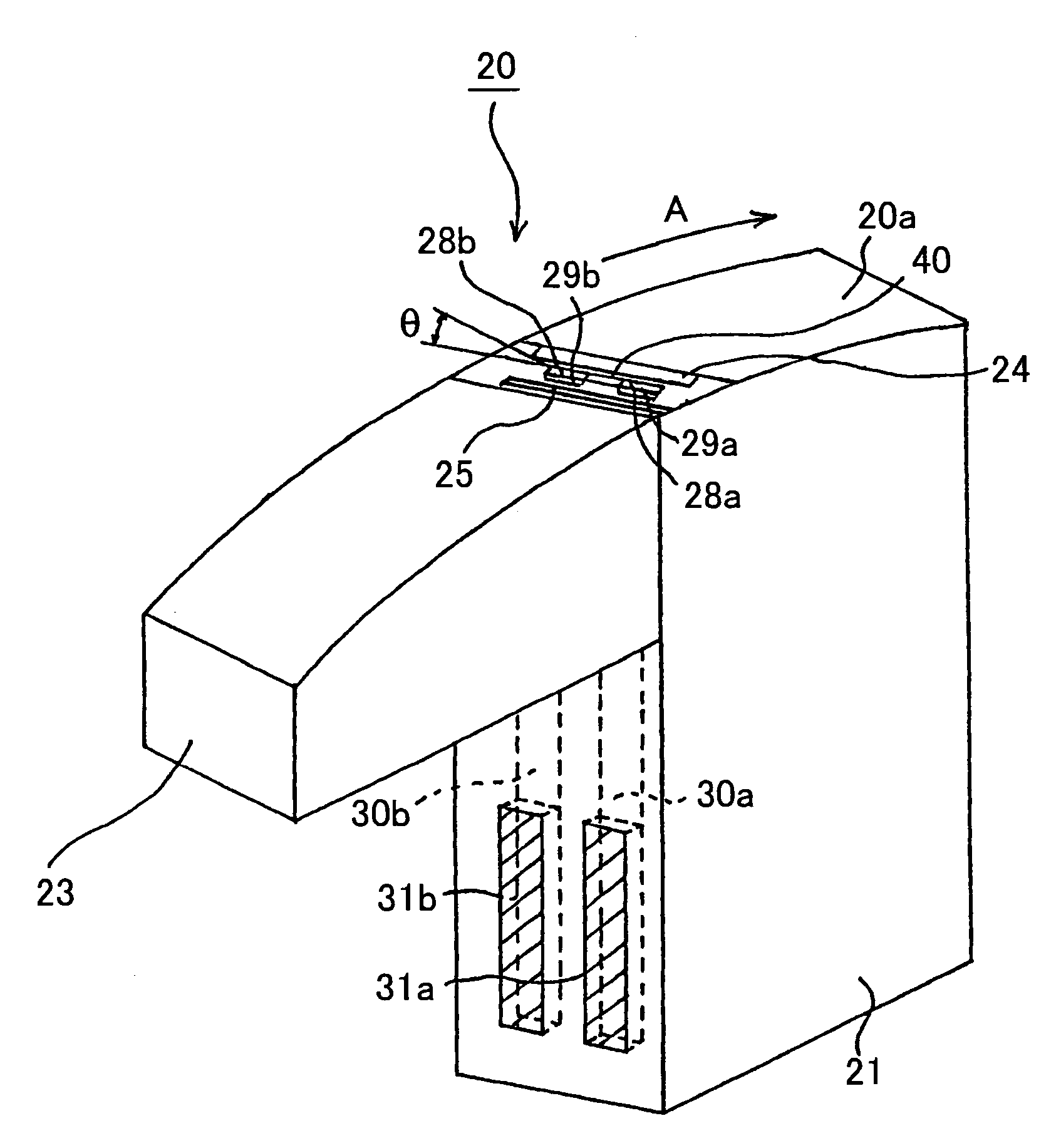
[0250]More specifically, a modified 8-mm VTR was used. Information signals were recorded on each of the sample tapes at a recording wavelength of 0.4 μm. Then, reproduced output, noise level, and S / N ratio were measured using the shield type GMR head 20.

[0251]The various conditions ...


PUM

PropertyMeasurementUnit
residual magnetization Mraaaaaaaaaa
corrosion potentialaaaaaaaaaa
mean roughness Rzaaaaaaaaaa

Abstract

A highly reliable magnetic recording / reproducing apparatus is provided. In the magnetic recording / reproducing apparatus, a spin-valve film is used as a magnetic sensor element for detecting magnetic signals. By defining the corrosion potential of this spin-valve film, and further by specifying the residual magnetization of a magnetic recording medium used as well as the product of the residual magnetization and the thickness of the magnetic layer to a range that is numerically optimal, the occurrence of corrosion on the surface of a magnetoresistive head that contacts the medium is prevented, and the occurrence of electromagnetic discharge is avoided. Further, by numerically specifying the surface resistivity of the metal magnetic thin film of the magnetic recording medium, as well as the roughness of the surface on which the metal magnetic thin film is formed, electrostatic discharge preventing effects and wear resistance are improved.

Description

CROSS REFERENCE TO RELATED APPLICATIONS[0001]The present document claims priority to Japanese Priority Document JP 2002-370518, filed in the Japanese Patent Office on Dec. 20, 2002, and on Japanese Priority Document JP 2003-111614, filed in the Japanese Patent Office on Apr. 16, 2003, the entire contents of which are incorporated herein by reference to the extent permitted by law.BACKGROUND OF THE INVENTION[0002]1. Field of the Invention[0003]The present invention relates to a magnetic recording / reproducing apparatus that is equipped with a magnetoresistive head that uses a spin-valve film as a magnetic sensor element for detecting magnetic signals while in contact with a magnetic recording medium.[0004]2. Description of the Related Art[0005]As magnetic sensor elements that detect the magnetic fields of signals from a magnetic recording medium, magnetoresistive elements (hereinafter referred to as MR elements) that utilize magnetoresistive effects where the resistance changes depend...

Claims


Application Information

Patent Timeline
Patent Type & Authority Patents(United States)
IPC IPC(8): G11B5/39G11B5/008G11B5/31G11B5/40G11B5/53G11B5/78
CPCB82Y10/00G11B5/40G11B5/53G11B5/78G11B5/3903G11B5/00813G11B5/0086G11B5/3106Y10T428/115Y10T428/1143
Inventor TETSUKAWA, HIROKISODA, YUTAKA
Owner SONY CORP
Why Eureka
Try Eureka