Method of forming a nanocomposite coating

a technology of nanocomposite coating and nano-composite coating, which is applied in the direction of superimposed coating process, natural mineral layered products, transportation and packaging, etc., can solve the problems of affecting the value of such products, requiring high temperature treatment for a long time, and easily scratching or otherwise damaging the surface of stainless steel in daily us

Inactive Publication Date: 2006-02-21
MAXFORD TECH LTD
View PDF12 Cites 15 Cited by
  • Summary
  • Abstract
  • Description
  • Claims
  • Application Information

AI Technical Summary

Problems solved by technology

As a result of this relatively low degree of hardness, stainless steel surfaces are easily scratched or otherwise damaged in daily use.
The appearance and attractiveness of the aforesaid items, in particular watch cases and watch bracelets, will be blemished, thus affecting the value of such products.
Both processes, however, require high temperature treatments for a long period of time.
As discussed above, long treatment time and high treatment temperature are required for nitridation and carburization, thus decreasing throughput and production efficiency, and increasing the production cost.
As there is no fresh supply of chromium, the formation of chromium nitride or chromium carbide will deplete the chromium content in the original stainless steel grain, thus adversely affecting the corrosion resistance capability of the treated stainless steel.
Secondly, nitridation and carburization can take place only on austenite stainless steel substrates, which are with high original chromium concentration, but not on martensite stainless steel substrates.
Thirdly, in order to enhance the efficiency of diffusion, the surface concentration of either nitrogen or carbon in the treated stainless steel is rather high, thus darkening or blemishing the surface of the treated stainless steel.
Such treatment is usually performed manually, thus lacking control and consistency.
However, again, the surface colour of the so-treated stainless steel differs appreciably from that of usual stainless steel, thus hindering the mass acceptance of products made of such treated stainless steel in the market.
Metallic hard chromium electroplating is only possible for application on copper and its alloys.
Aluminum and its alloys, magnesium and its alloys, and titanium and its alloys oxidize rapidly in electrolytic solutions, and become electrically un-conductive, thus preventing electroplating.
Furthermore, PVD of ceramics such as carbide or nitride uses radio frequency (RF) power supplies, e.g. at a frequency of 13.56 MHz, and the low deposition rates add much to the manufacturing cost.

Method used


Image

  • Method of forming a nanocomposite coating
  • Method of forming a nanocomposite coating
  • Method of forming a nanocomposite coating

Examples


example 1

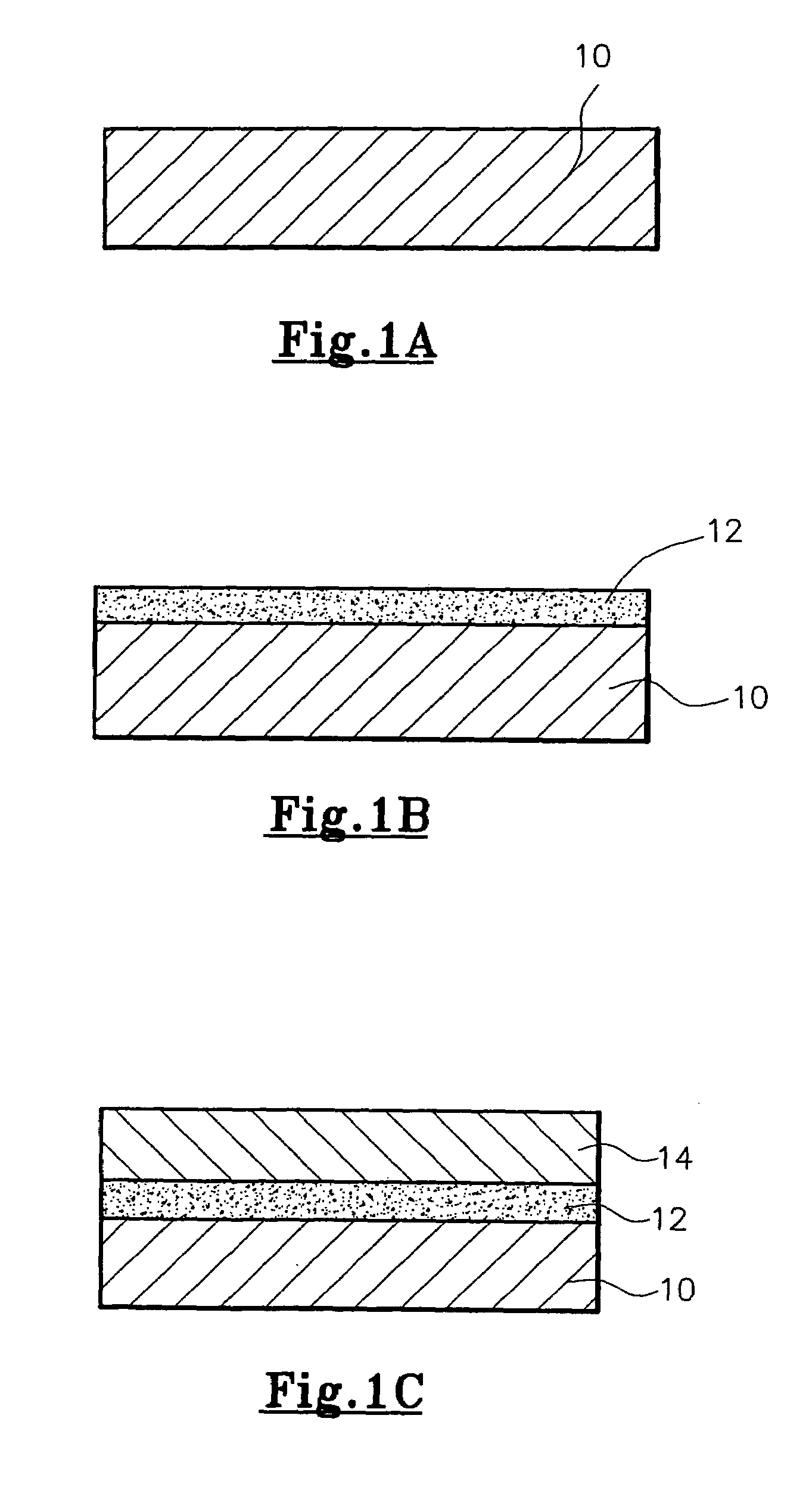
[0033]Stainless steel watch bracelets were first de-waxed and thoroughly cleaned, and then placed on the carriers 110 of the ion-sputtering apparatus 100. After closing the door 108, the chamber 102 was pumped down to a base pressure of 2×10⁻⁶ torr (i.e. mmHg; equivalent to around 2.666×10⁻⁴ Pa). During pumping down, the chamber 102 was heated up to 300–350° C. When the required base pressure of 2×10⁻⁶ mmHg (i.e. around 2.666×10⁴ Pa) was reached, argon (Ar) gas was introduced into the chamber 102 and the pressure in the chamber 102 was raised to 5×10⁻³ torr (i.e. around 0.667 Pa). A negative biasing voltage of 600–800 volts was applied to the watch bracelets, which initiated bombardment of argon atoms onto the watch bracelets, to thereby remove any residual contaminants from the surface of the watch bracelets.

[0034]The switchable power source 120 was then connected to the double-sided pure titanium target 122, whereby a thin layer (of a thickness of from 0.02 to 0.20 micron) of tita...

example 2

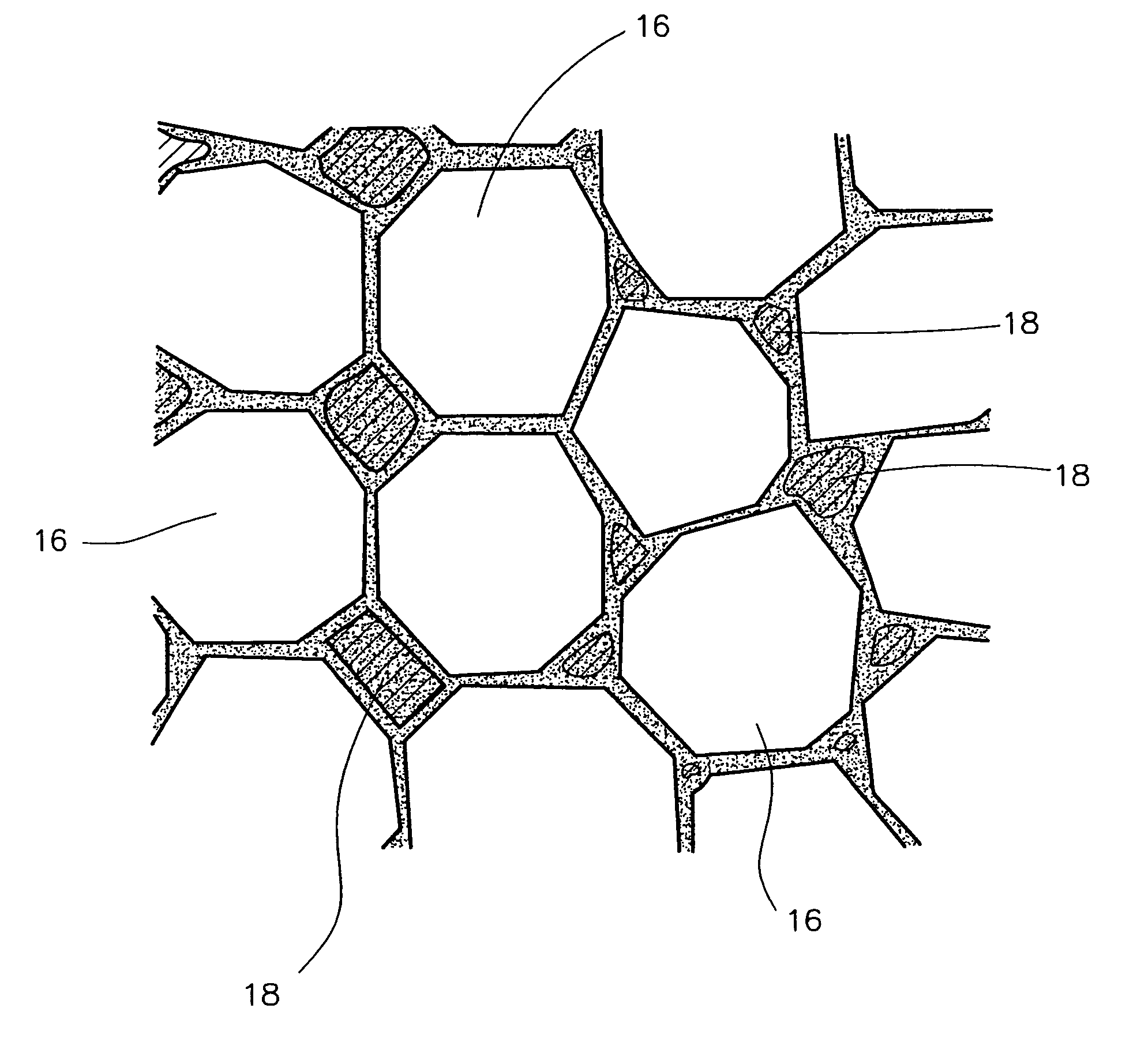
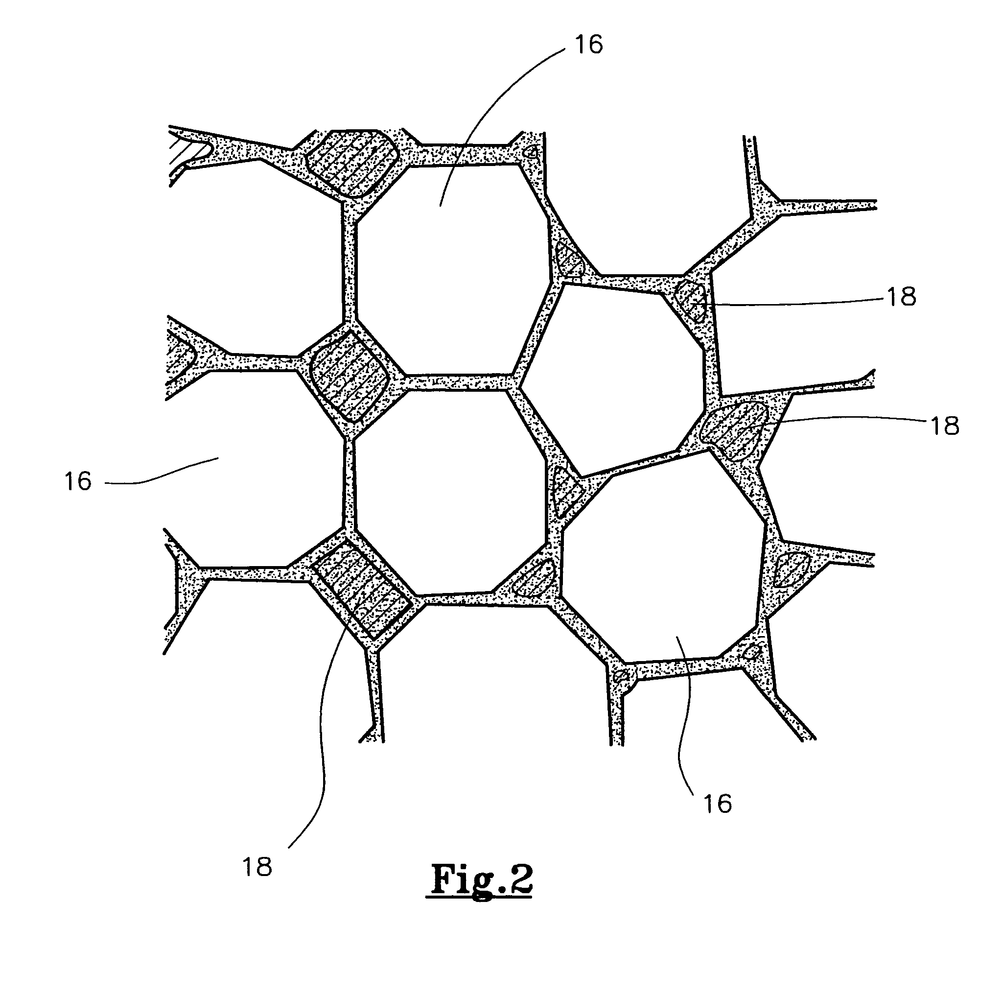
[0038]Instead of using pure stainless steel and chromium targets, as discussed in Example 1 above, alloy targets of stainless steel and chromium were used. The alloy targets contained 40–60 wt. % of stainless steel, with the rest being chromium. The process was very similar to that discussed in Example 1 above, except that stainless steel and chromium particles were co-sputtered reactively in a carbon gas plasma, forming adjacent molecules of stainless steel and chromium carbide. Again, when the stainless steel articles, which were watch cases in the present Example, were away from the deposition locations, the stainless steel and chromium carbide molecules relaxed into their most thermodynamically suitable sites, thus forming the nanocomposite structure of hard stainless steel and chromium carbide coating.

example 3

[0039]Stainless steel watch casings were first de-waxed and thoroughly cleaned, and then placed on the carriers 110 of the ion-sputtering apparatus 100. After closing the door 108, the chamber 102 was pumped down to a base pressure of 2×10⁻⁶ torr (around 2.666×10⁻⁴ Pa). During pumping down, the chamber 102 was heated up to 300–350° C. When the required base pressure of 2×10⁻⁶ mmHg (i.e. around 2.666×10⁻⁴ Pa) was reached, argon (Ar) gas was introduced into the chamber 102 and the pressure in the chamber 102 was raised to 5×10⁻³ torr (i.e. around 0.667 Pa). A negative biasing voltage of 600–800 volts was applied to the watch casings, which initiated bombardment of argon atoms onto the watch casings, to thereby remove any residual contaminants from the surface of the watch casings.

[0040]The switchable power source 120 was then connected to the double-sided pure titanium target 122, whereby a thin layer (of a thickness of from 0.02 to 0.20 micron) of titanium was first deposited onto th...


PUM

PropertyMeasurementUnit
thicknessaaaaaaaaaa
biasing voltageaaaaaaaaaa
temperatureaaaaaaaaaa

Abstract

There is disclosed a method of depositing a nanocomposite coating of stainless steel and a metallic carbide or metallic nitride, e.g. chromium carbide or chromium nitride, onto a stainless steel substrate 10, including the steps of (a) providing the stainless steel substrate 10; (b) depositing stainless steel on the substrate 10; (c) depositing chromium carbide or chromium nitride on the substrate 10; and allowing a nanocomposite coating 14 of the stainless steel and chromium carbide or chromium nitride to form on the substrate 10.

Description

[0001]This invention relates to a method of coating or depositing a layer of stainless steel nanocomposite coating onto a substrate, in particular a solid metal or metal alloys substrate, and an article so coated.BACKGROUND OF THE INVENTION[0002]Stainless steel is used in a large number of applications and industries, including such wearable, ornamental or portable items as watch cases, watch bracelets, bracelets, eye-glass frames, jewelry items, and mobile phones. For aesthetic reasons, various surface finishes, such as polished, satin, and sand-blasted, are employed.[0003]Stainless steel is usually of a hardness of 200 HV under the Vicker scale. As a result of this relatively low degree of hardness, stainless steel surfaces are easily scratched or otherwise damaged in daily use. The appearance and attractiveness of the aforesaid items, in particular watch cases and watch bracelets, will be blemished, thus affecting the value of such products.[0004]Various methods have thus been de...

Claims


Application Information

Patent Timeline
Patent Type & Authority Patents(United States)
IPC IPC(8): B32B15/00B32B15/04C23C14/16C23C14/34B82B3/00C23C14/02C23C14/06
CPCC23C14/025C23C14/0688C23C28/34C23C28/322Y10T428/12979Y10T428/12576
Inventor CHAN, WINSTON SIU YEUNG
Owner MAXFORD TECH LTD
Why Eureka
Try Eureka