Solid electrolytic capacitor and manufacturing method of the same

a technology of solid electrolytic capacitors and manufacturing methods, which is applied in the direction of liquid electrolytic capacitors, wound capacitors, fixed capacitors, etc., can solve the problems of capacitors having a high achievement ratio, affecting the performance of capacitors, so as to reduce the tan and esr, and reduce the interface resistance between cathode foils and conducting polymers

Active Publication Date: 2006-02-28
NICHICON CORP
View PDF10 Cites 16 Cited by
  • Summary
  • Abstract
  • Description
  • Claims
  • Application Information

AI Technical Summary

Benefits of technology

[0016]The present invention has an object to provide a solid electrolytic capacitor being superior in frequency response and having a high capacity.
[0018]With the above-mentioned configuration, the cathode foil is not directly in touch with the conducting polymer layer, but the cathode foil is in touch with the conducting polymer layer through an organic matter, the carbide grains. Adhesiveness between the cathode foil and the conducting polymer layer is advanced. In addition, a void between the carbide grains is larger than an etching pit of an ordinary oxide layer. And the conducting polymer layer is formed effectively. Accordingly, the interface resistance between the cathode foil and the conducting polymer layer is reduced, and it is possible to reduce the tanδ and the ESR. In addition, the cathode foil, the carbide grains and the conducting polymer layer are conducted electrically during an energization of the solid electrolytic capacitor. The carbide grains and the conducting polymer layer do not affect the capacity as a cathode of the solid electrolytic capacitor. And the anode side electrical capacity is combined capacity of the solid electrolytic capacitor. It is possible to advance a capacity achievement ratio of the solid electrolytic capacitor in accordance with the present invention.
[0020]In accordance with the present invention, it is possible to make the cathode foil be in touch with the conducting polymer layer through an organic matter, the carbide grains. The adhesiveness between the cathode foil and the conducting polymer layer is advanced. In addition, the void between the carbide grains is larger than the etching pit of the ordinary oxide layer. And the conducting polymer layer is formed effectively. Accordingly, the interface resistance between the cathode foil and the conducting polymer layer is reduced, and it is possible to reduce the tanδ and the ESR.

Problems solved by technology

That is, even if the cathode having high capacity is used, the combined capacity never exceeds the capacity of the anode, and an increase of the capacity is limited.
In addition, in a case where a conducting polymer layer, which is dense and has a high yield point, cannot be formed, a capacitor having a high achievement ratio cannot be obtained.
In addition, there is a problem that an expansion of a metal case or a closing rubber occurs and features degrades, if the solid electrolytic capacitor mentioned above is used for a surface mounted chip parts of portrait style or transverse style and is subjected to soldering at reflow.
However, the arrangements disclosed in Documents 1 and 2 have a problem that a cost merit degrades.
Because the metal nitride and the valve metal are expensive and there is a need for pretreating the cathode and treating the cathode during the manufacturing process.
Therefore, it is not possible to reduce the ESR and the tanδ.
Further, the coated carbide material is detached easily, which causes a problem that feature degradation is promoted through long-term use.
In addition, the arrangements of Document 5 and 6 have a problem that an increase of a capacity is limited.
Because reduction of density of the resin having heat resistance is limited and conducting polymer cannot be filled sufficiently.

Method used


Image

  • Solid electrolytic capacitor and manufacturing method of the same
  • Solid electrolytic capacitor and manufacturing method of the same
  • Solid electrolytic capacitor and manufacturing method of the same

Examples


example 1

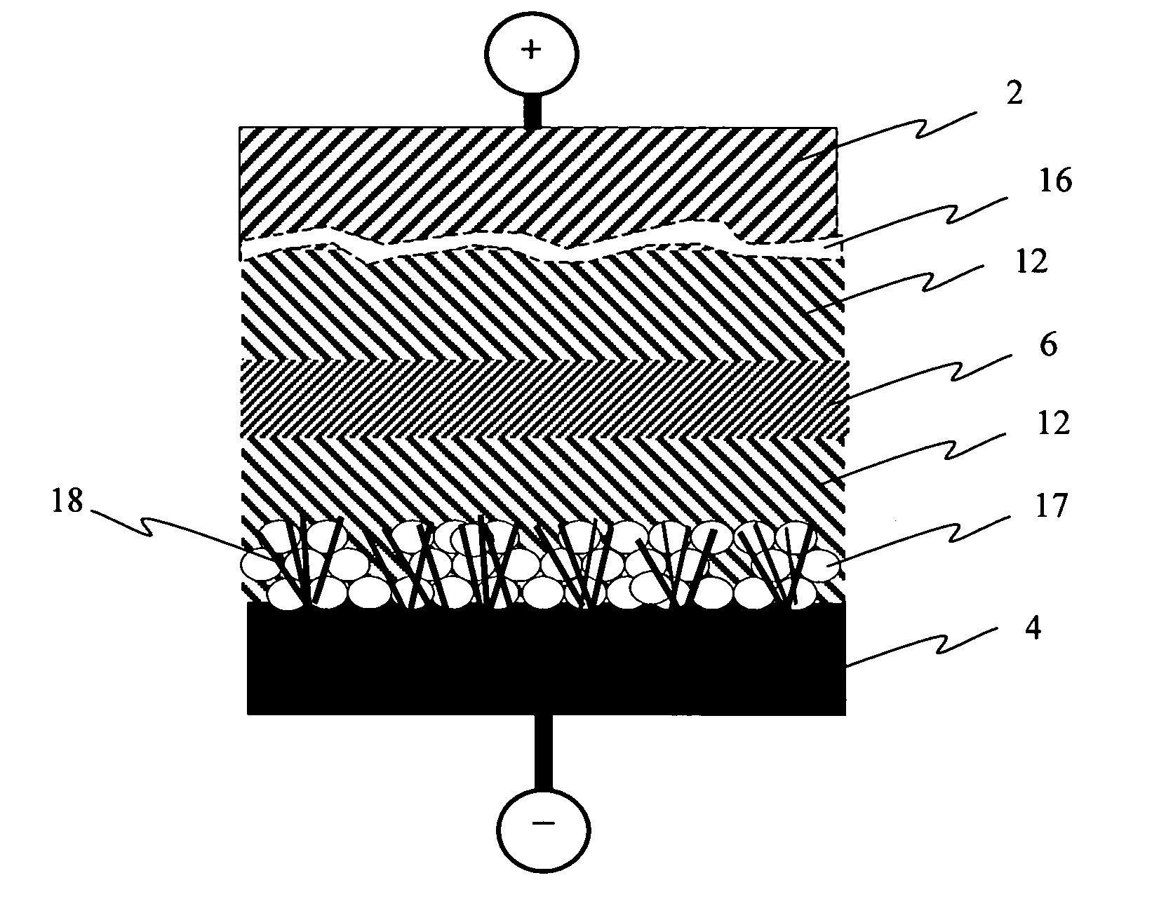
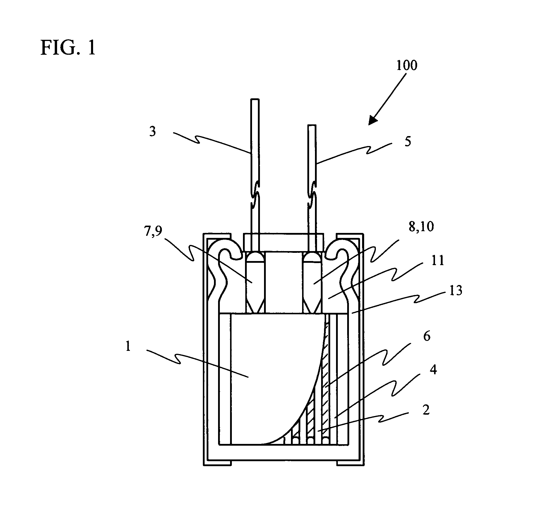
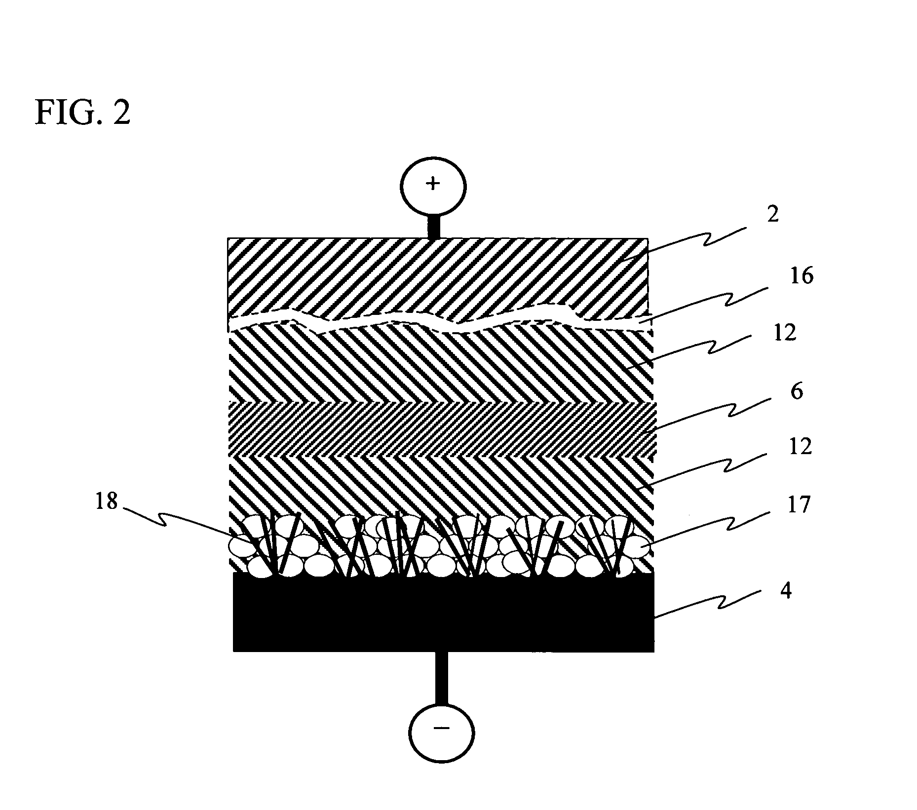
[0043]In an example 1, the solid electrolytic capacitor 100 shown in FIG. 1 was formed. The anode foil 2 was formed of an aluminum foil, which was subjected to an etching treatment and a chemical treatment and had 0.7 cm width, 11.5 cm length, and 100 μm thickness. The cathode foil 4 was formed of an aluminum, which had 0.7 cm width, 13.1 cm length and 50 μm thickness. Whiskers were formed on the surface of the cathode foil 4. The whiskers held carbide grains. The thickness of the layer where the carbide grains were held was 2 μm. An electrolytic paper mainly formed of Manila fiber was used for the separator paper 6. The normal rated voltage of the capacitor 1 was 4WV.

[0044]Next, after rolling the anode foil 2 and the cathode foil 4 together across the separator paper 6, the anode foil 2 was subjected to a chemical treatment at a voltage near the formation voltage of the dielectric oxide layer of the anode foil 2 using chemical liquid mainly containing 0.5% to 2% ammonium adipate by...

example 2

[0047]In an example 2, the solid electrolytic capacitor 100a shown in FIG. 3 was formed. The anode foil 2 was formed of an aluminum foil, which was subjected to an etching treatment and a chemical treatment and had 0.7 cm width, 17.5 cm length, and 110 μm thickness. The cathode foil 4 was formed of an aluminum, which had 0.7 cm width, 19.1 cm length and 50 μm thickness. Whiskers were formed on the surface of the cathode foil 4. The whiskers held carbide grains. The thickness of the layer in which the whiskers held the carbide grains was 2 μm. A nonwoven fabric formed of polyethylene terephthalate was used for the separator paper 6. The normal rated voltage of the capacitor 1 was 4WV.

[0048]Next, after rolling the anode foil 2 and the cathode foil 4 together across the separator paper 6, the anode foil 2 was subjected to a chemical treatment at a voltage near the formation voltage of the dielectric oxide layer of the anode foil 2 using chemical liquid mainly containing 0.5% to 2% ammo...


PUM

PropertyMeasurementUnit
thicknessaaaaaaaaaa
diameteraaaaaaaaaa
thicknessaaaaaaaaaa

Abstract

A solid electrolytic capacity has an anode foil 2 having dielectric oxide layer 16 formed on surface thereof, a cathode foil 4 having whiskers 18 that are formed on surface thereof and hold carbide grains 17, a separator paper 6 and solid electrolytic layers 12 formed of a conducting polymer. The anode foil 2 and the cathode foil 4 were rolled together across the separator paper 6. The solid electrolytic layers 12 are formed between the anode foil 2 and the cathode foil 4. Thickness of a layer where the whiskers 18 hold the carbide grains 17 is 1 μm to 5 μm. A method of manufacturing a solid electrolytic capacitor having steps of generating whiskers on surface of a cathode foil after coating carbide grains on the surface of the cathode foil and drying the carbide grains, rolling the cathode foil and an anode foil having dielectric oxide layer formed on surface thereof across a separator, impregnating polymerizable monomers and an oxidizing reagent into the separator, polymerizing the polymerizable monomers and forming solid electrolyte layers between the cathode foil and the anode foil.

Description

BACKGROUND OF THE INVENTION[0001]1. Field of the Invention[0002]This invention generally relates to solid electrolytic capacitors that may be used for a wide variety of electronics devices, and more particularly, to a roll-formed solid electrolytic capacitor and a surface-mounted solid electrolytic capacitor having a solid electrolyte formed of conducting polymer.[0003]2. Description of the Related Art[0004]Recently, there are demands for enhancing capacity of an electrolytic capacitor, for downsizing the electrolytic capacitor and further for lowering impedance at higher frequencies of the electrolytic capacitor, as electronics devices are digitalized.[0005]The solid electrolytic capacitor has an excellent frequency characteristic relative to other electrolytic capacitors, and thus attracts attentions. A chemical coat mainly formed of valve metal like aluminum or tantalum is used as an anode in the solid electrolytic capacitor. One of typical structures of the solid electrolytic ca...

Claims


Application Information

Patent Timeline
Patent Type & Authority Patents(United States)
IPC IPC(8): H01G4/32H01G9/00H01G9/145H01G4/00
CPCH01G9/0425H01G9/151H01G9/045Y10T29/417H01G9/02H01G9/15
Inventor UEDA, AKIRAYAMADA, KATSUHARUFUNAHASHI, MINORU
Owner NICHICON CORP
Why Eureka
Try Eureka