[0009]Conventional methods for measuring overlay errors employ
high numerical aperture objectives for collecting light from two target structures, where
high numerical aperture objectives are used to maximize the resolution and hence the edge definition. The target structures may include an inner box at a higher elevation compared to the outer box. Since the collection objective employed in conventional methods has a high
numerical aperture, this necessarily means that it has a small
depth of focus. Thus, if the objective is positioned so that radiation from the inner box is focused onto the
detector, then light collected from the outer box at a lower elevation will be out of focus with respect to the
detector. Hence, in order to accurately measure both the inner and outer boxes, it is necessary to measure the target twice, known in the field as “double grab” with different optical focuses, so that radiation from both the inner and outer boxes may be focused onto the
detector. Since two measurements are required instead of one as in a “single grab” measurement, this adversely affects
throughput and is disadvantageous. Furthermore, where the detection system is subject to vibrations, such as in a wafer
processing environment, vibrations may cause the
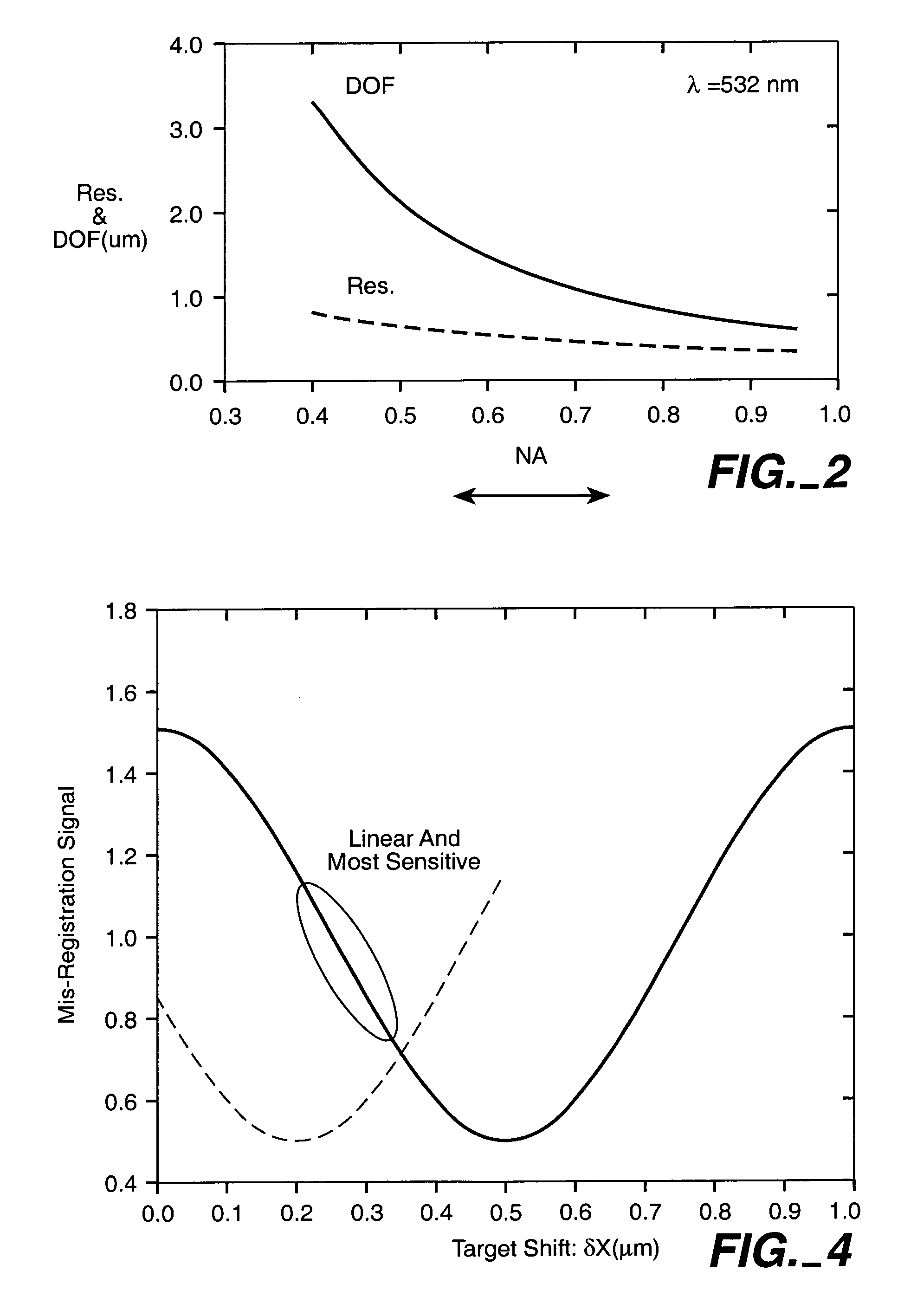
optical alignment to shift between the two measurements, which may result in errors in the overlay error measurement. According to another aspect of the invention, the collection objective has a medium
numerical aperture and therefore a larger depth of focus. Hence this increases the likelihood that radiation from both the inner and outer boxes or other structures at different elevations will be adequately focused onto corresponding detectors simultaneously so that there is no need to measure the target twice. Therefore, there are more applications where single grab is possible so that
throughput is not adversely affected for such applications. Furthermore, since a medium numerical aperture increases the
odds for adequate information to be obtained for overlay error measurement in one measurement, the system is robust and less affected by vibrations.
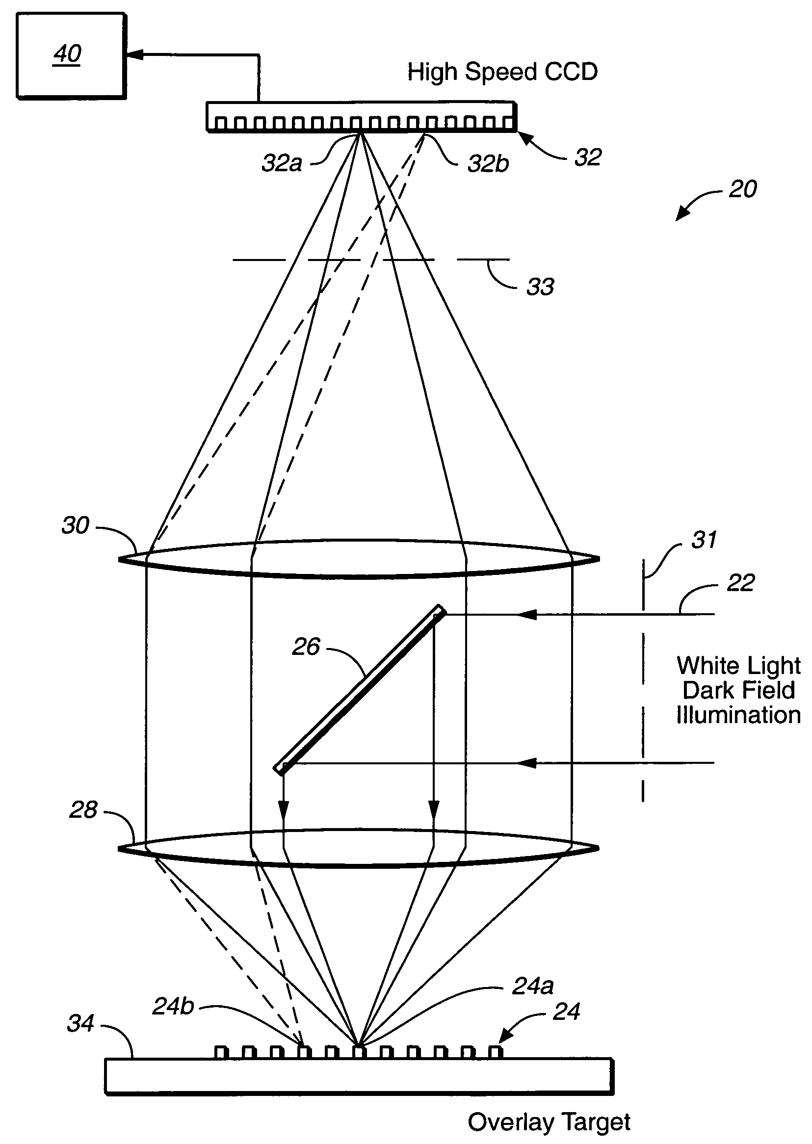
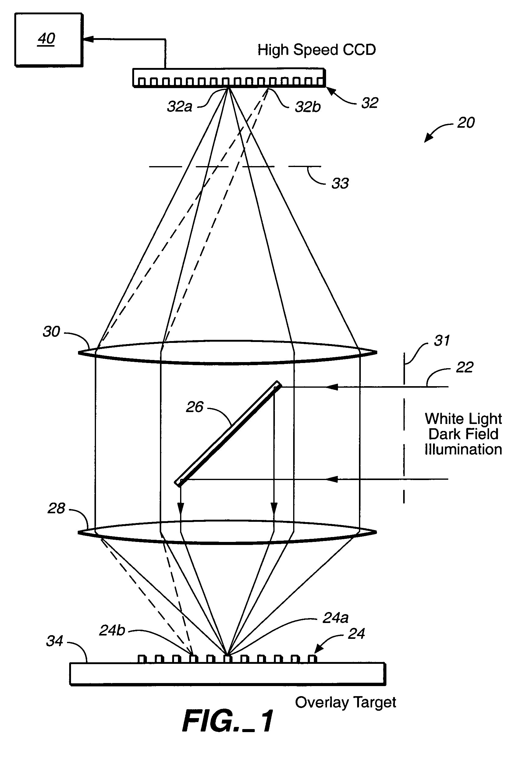
[0014]According to another aspect of the invention, radiation that is imaged onto the array of detectors is collected only along one or more directions away from the
specular reflection direction(s) for the reason that such detection suppresses
low spatial frequency components and brings up high spatial frequencies, which increases the
edge detection capability and hence the sensitivity in the overlay error measurement. A detection system employing such collection (collecting only along one or more directions away from the
specular reflection direction(s)) is referred to as a dark field system, which is useful for measuring overlay errors of periodic type targets such as gratings, as well as targets employing box(es) and bar(s), such as box-in-box and bar-in-bar type targets. Dark field systems are particularly useful for measuring overlay errors in
low contrast targets, such as where the difference in elevation between the inner and outer boxes is small.
[0016]In conventional processing of data in overlay error detection, only data in portions of images at or close to edges of objects such as boxes or bars are used and the system is strongly dependent on the quality and contrast of the images. Modern chemical mechanical
polishing processes tend to reduce the contrast of the target so that conventional methods may no longer be adequate. According to another aspect of the invention, the two-dimensional image of the target is represented by at least one
signal which is an analytical function of position in the image. A
curve fitting process of the at least one
signal to data from the image of the two structures is then preferably used to determine an overlay error. When the image of the two structures is represented by at least one
signal which is an analytical function, more information from the two-dimensional image is used for finding overlay errors compared to conventional methods and yields more accurate results. The
curve fitting process further improves detection
accuracy and precision.

