
Multiplexer hardware and software for control of a deformable mirror

a technology of deformation mirror and multi-layer hardware, which is applied in the direction of program control, electric controller, instruments, etc., can solve the problems of reducing the size, weight, power consumption and cost of the deformation mirror driver electronics system, and reducing the number of amplifiers. , the effect of facilitating the reduction of the number of amplifiers

Inactive Publication Date: 2006-03-14
SOLVISIONS TECH INTL
View PDF6 Cites 20 Cited by
  • Summary
  • Abstract
  • Description
  • Claims
  • Application Information

AI Technical Summary

Benefits of technology

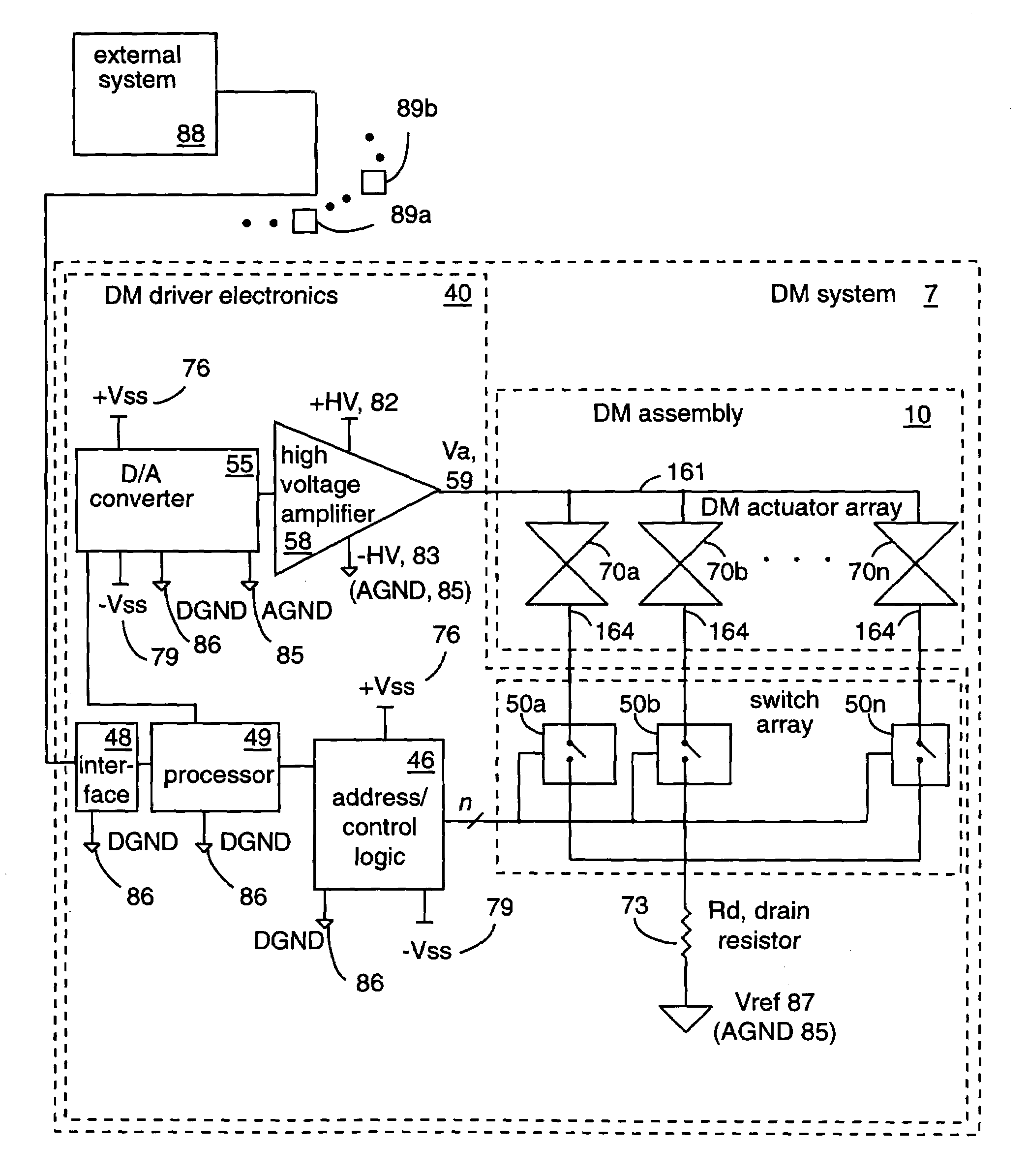
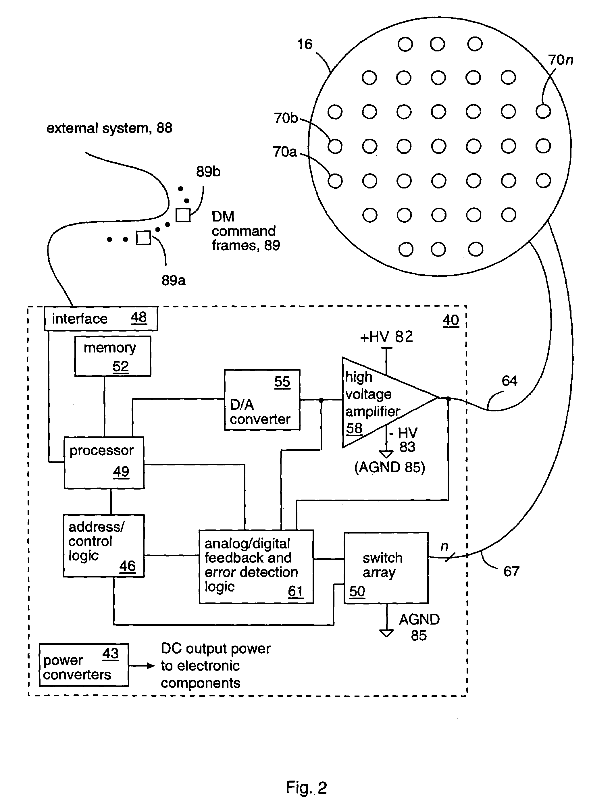
[0012]The capacity of actuators to store a charge, and therefore maintain a length during operation for a given amount of time, can be leveraged to reduce the size, weight, power consumption, and cost of a deformable mirror (DM) driver electronics system. The number of amplifiers can be reduced from one amplifier per actuator in a DM actuator array to as few as one amplifier per entire DM actuator array. To facilitate the reduction in the number of amplifiers, at least one amplifier controls one or more DM actuators at a time when providing actuator command updates to the DM.
[0013]The longer the DM actuators are able to maintain their lengths (i.e., store a charge), the more the control rate can be reduced for controlling the DM actuators in the DM actuator array and still maintain a given DM surface figure within an error tolerance between command updates (i.e., while not under amplifier control). In addition, the DM driver electronics used to control the lengths of the DM actuators must not significantly affect the stored respective charges on the actuators between command updates.
[0015]The at least one processing unit provides many functions, including coordinating (i) selecting states of switches to enable DM actuators with (ii) commanding signals to the high voltage amplifier. When properly coordinated, the switches and amplifier(s) drive the deformable mirror with very low risk of electrical failure of the switches, amplifier(s), and / or actuators.
[0021]The driver electronics may be packaged in various configurations. For example, the electronics may be packaged into the DM assembly, separated from the mirror mechanical assembly by thermal insulation. Various components, such as the addressing circuitry and / or switches, can be packaged in ASICs, FPGA's, or hybrid microelectronics. In one embodiment, aspects of the DM driver electronics are coupled directly to blocks of high-density actuators. High density power converters may be employed to further reduce size and weight of the electronics while possibly improving power efficiency.
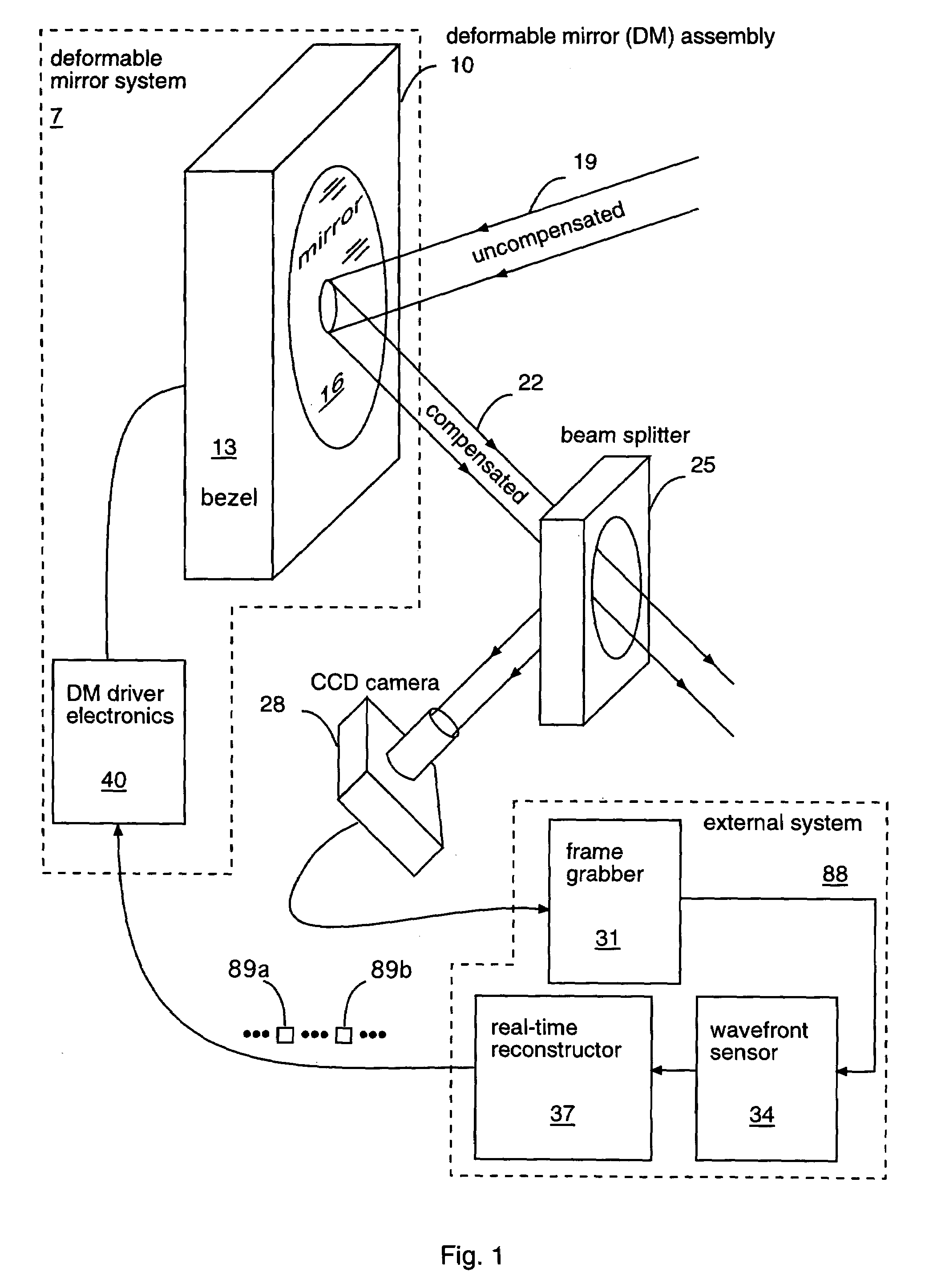
[0022]The DM subsystem comprising the multiplexer DM driver electronics may be integrated with other subsystems to form a closed-loop adaptive optics system. The closed-loop adaptive optics system may be employed by larger systems, such as space-based telescopes, ground-based telescopes, precision optical instruments, energy-production systems such as nuclear fusion generation systems, communication systems, and medical instruments, thereby taking advantage of the size, weight, power efficiency, cost, and space-readiness of a multiplexed DM.

Problems solved by technology

Thus, a high stroke requirement for an actuator results in a relatively high current to generate a high rate of change of the length of the actuator.
In most applications, high capacitance of an actuator tends to be a bad quality (e.g., high power requirements) with respect to operation of the system in which the actuator is deployed.
In the past, the challenge for the adaptive optics community, specifically deformable mirror developers, has been to increase the bandwidths of traditional adaptive optics systems to correct optical phase error in high turbulence atmospheric conditions, which necessarily leads to driving a deformable mirror at higher frame rates and amplifiers and actuators at higher bandwidths.
Low bandwidth applications raise issues related to the DM driver electronics that were not of serious concern in the high bandwidth applications, such as: size, weight, power consumption, packaging, radiation-hardening, and cost.

Method used


Image

  • Multiplexer hardware and software for control of a deformable mirror
  • Multiplexer hardware and software for control of a deformable mirror
  • Multiplexer hardware and software for control of a deformable mirror

Examples


Embodiment Construction

[0060]The present invention is described more fully hereinafter with reference to the accompanying drawings, in which preferred embodiments of the invention are shown. This invention may, however, be embodied in many different forms and should not be construed as being limited to the embodiments set forth herein; rather, these embodiments are provided so that this disclosure will be thorough and complete, and will fully convey the scope of the invention to those skilled in the art.

[0061]Some of the issues / goals for DM driver electronic systems in low bandwidth or weight / power-limited adaptive optics systems applications include: low weight, small size, low power consumption, low thermal output, deep space compatability / capability (radiation-hardened circuitry), high packaging density / diversity, high mean-time between failure, and low cost. One approach to achieving these goals is to change the amplifier design of traditional DM driver electronics systems from a high bandwidth amplif...


PUM


Abstract

A multiplexer (MUX) driver system controls a deformable mirror, in part, by enabling and disabling individual or multiple actuators, mechanically coupled to the deformable mirror, through use of switches (e.g., solid-state switches) electrically coupled between the actuators and a reference node. In operation, the driver system enables actuator(s) by closing respective switch(es) and driving the enabled actuator(s) to deform respective portions of the deformable mirror in a controlled manner. The driver system disables the actuator(s) by opening the respective switch(es) to decouple the actuator(s) from the reference node. The switches, in the open state, prevent respective actuators from discharging, thereby allowing a desired surface figure of the deformable mirror to be maintained for long periods of time without having to refresh the actuators. The multiplexer driver system supports low-power modes of operation and is well suited for driving a deformable mirror in larger systems, such as space-based telescopes.

Description

BACKGROUND OF THE PRESENT INVENTION[0001]Real-time adaptive optics is a control process generally used to reduce optical phase error in an optical transmission system, such as a telescope or a laser beam director. In high bandwidth applications, such as astronomy and remote sensing, the goal of real-time adaptive optics is to operate at high frequencies to compensate for high bandwidth atmospheric distortion and to produce stable, high fidelity images. High-performance, real-time, adaptive optics systems include sensors, processors, and dynamic mirror assemblies, optionally including vibration compensation mirrors (i.e., fast steering mirrors that provide tip and tilt motions) and / or phase error compensation mirrors (i.e., deformable mirrors that provide surface figure adjustments). High-speed communications, high-bandwidth electronics, and high-bandwidth control systems are used to control both fast steering and deformable mirrors within the high-performance, real-time, adaptive op...

Claims


Application Information

Patent Timeline
Patent Type & Authority Patents(United States)
IPC IPC(8): G05B11/01G02B26/08
CPCG02B26/0825G02B26/06
Inventor SOLOMON, MARK B.
Owner SOLVISIONS TECH INTL
Learn More