Catheter for radiation therapy

a radiation therapy and catheter technology, applied in the field of catheters for radiation therapy, can solve the problems of repeated stenosis, i.e. a high probability, an aneurysm, necrosis of the blood vessel, etc., and achieves the effect of no risk of the inner surface of the blood vessel being damaged and little resistance to movement through the blood vessel

Inactive Publication Date: 2006-06-06
KANEKA CORP
View PDF14 Cites 35 Cited by
  • Summary
  • Abstract
  • Description
  • Claims
  • Application Information

AI Technical Summary

Benefits of technology

[0018]It is an object of the present invention to provide a catheter for radiation therapy according to which the problems described above can be avoided or reduced. That is, it is an object of the present invention to provide a catheter for radiation therapy that has a centering mechanism that enables blood vessel walls to be irradiated with a uniform radiation dose, and has a perfusion mechanism that allows blood to flow to peripheral blood vessels at all times during centering, and for which there are no undulations on the surface of the catheter when the catheter is being moved through a blood vessel, and hence there is little resistance to movement through the blood vessel, and there is no risk of the inner surface of the blood vessel being damaged, and moreover for which manufacture is easy.

Problems solved by technology

However, there is a large problem with this PTCA therapy in that after the therapy, restenosis, i.e. repeated stenosis, occurs with a probability of approximately 40% within a short time period of 3 to 6 months.
It has been shown that restenosis is caused by the blood vessel walls being damaged through the forcible expansion of the blood vessel by the balloon, and then smooth muscle cells proliferating excessively during the subsequent healing process.
Regarding irradiating the blood vessel walls uniformly, if the radiation source shifts away from the center of the blood vessel cross section when the radiation source is positioned at the lesioned part in the blood vessel, then the blood vessel wall that is too close to the radiation source will be irradiated excessively, resulting in necrosis of the blood vessel, an aneurysm or the like.
In the case that such a long time is required as the irradiation time, if the coronary artery blood were not to flow to the peripheral coronary artery blood vessels during the irradiation, then the myocardial cells in peripheral parts would become ischemic, causing serious symptoms such as angina.
However, in the case of these spiral lobes (the spiral balloon), unless special measures are adopted, problems and inconveniences such as the following arise.
A first problem is that if the thickness of the balloon is constant in the circumferential direction after molding, then in the balloon's natural expanded state, the balloon will not be a spiral shape, but rather will be a straight shape.
Consequently, when one attempts to wind the balloon in a spiral fashion around the catheter shaft and fix the balloon using an adhesive or the like, the balloon tries to return to its natural straight shape, and hence the fixing of the balloon in a certain position on the surface of the catheter shaft is difficult, i.e. there is a difficulty in terms of fixing the balloon precisely in position, and hence reproducibility is poor.
This is a big disadvantage from a manufacturing perspective in particular in the case of using an adhesive having a long hardening time.
Moreover, if the spiral balloon is not fixed precisely in position, i.e. if places exist where the groove width is too large, then the precision of the centering will tend to become poor, which is a serious problem from a clinical perspective.
A second problem is that when fixing the straight balloon onto the catheter shaft such that the balloon goes into a spiral state, it is necessary to twist the balloon slightly forcibly.
In such a case, the time for which the radiation source is in the twisted part of the shaft will become long, and hence the patient's exposure to radiation at this part will increase, which is not only a large problem in terms of safety, but moreover it will no longer be possible to irradiate the region to be treated with radiation effectively.
A third problem is that when the balloon has been expanded, there will be a large stress in the balloon due to trying to return to the natural straight state, and in the case that the expansion pressure is high, there will be a risk of the balloon dropping off the shaft due to this stress.
These may be serious problems from a clinical perspective.
A fourth problem is that before the balloon is expanded, and when the balloon has been expanded and then contracted, there are large level differences on the outer surface.
In particular, the level differences on the balloon part after the balloon has been expanded and then contracted are marked, resulting in a large resistance when moving through a blood vessel.
Moreover, in the worst cases, the inside of the blood vessel may be damaged.
However, problems and inconveniences such as the following arise with the structure disclosed in Japanese Patent Application Laid-open No. 10-179751.
A first problem is that the shape of the centering balloon consists of spokes that are long in the axial direction; when the centering balloon is expanded, the balloon tries to return to its natural straight shape, and hence this part becomes rod-like and hard.
In the case for example that the lesioned part to be treated is an extremely curved blood vessel, the balloon may lose out to the curvature of the blood vessel and may thus not expand sufficiently to realize perfusion, and moreover the blood vessel may be irradiated excessively with radiation at the part where the balloon has not expanded sufficiently, which may cause necrosis of the blood vessel, an aneurysm or the like.
Moreover, the centering balloons, two or more of which are provided as described above, will not expand uniformly, and hence it will not be possible to realize the centering of the radiation source, and as a result part of the lesioned region to be treated may be irradiated excessively with radiation, which may cause necrosis of the blood vessel, an aneurysm or the like.
Furthermore, upon expanding the centering balloon, a force acts to straighten out the curved blood vessel, and with a peripheral blood vessel in particular the blood vessel may be damaged.
A second problem is that because a centering balloon having at least two expandable spokes is installed on the outer surface close to the tip of the catheter, even before expansion, the structure is such that there are large level differences on the outer surface of the balloon.
The catheter must proceed along a narrow, curved blood vessel as far as the region to be treated, but if there are large level differences around the catheter, then the ability of the surgeon to maneuver the catheter will be impaired, and it may not be possible to dispose the catheter in the region to be treated, and moreover the inside of the blood vessel may be damaged by the level differences.
Moreover, in the worst cases, the inside of the blood vessel may be damaged.

Method used


Image

  • Catheter for radiation therapy
  • Catheter for radiation therapy
  • Catheter for radiation therapy

Examples


Embodiment Construction

[0043]Following is a description of various embodiments of the catheter according to the present invention with reference to the drawings.

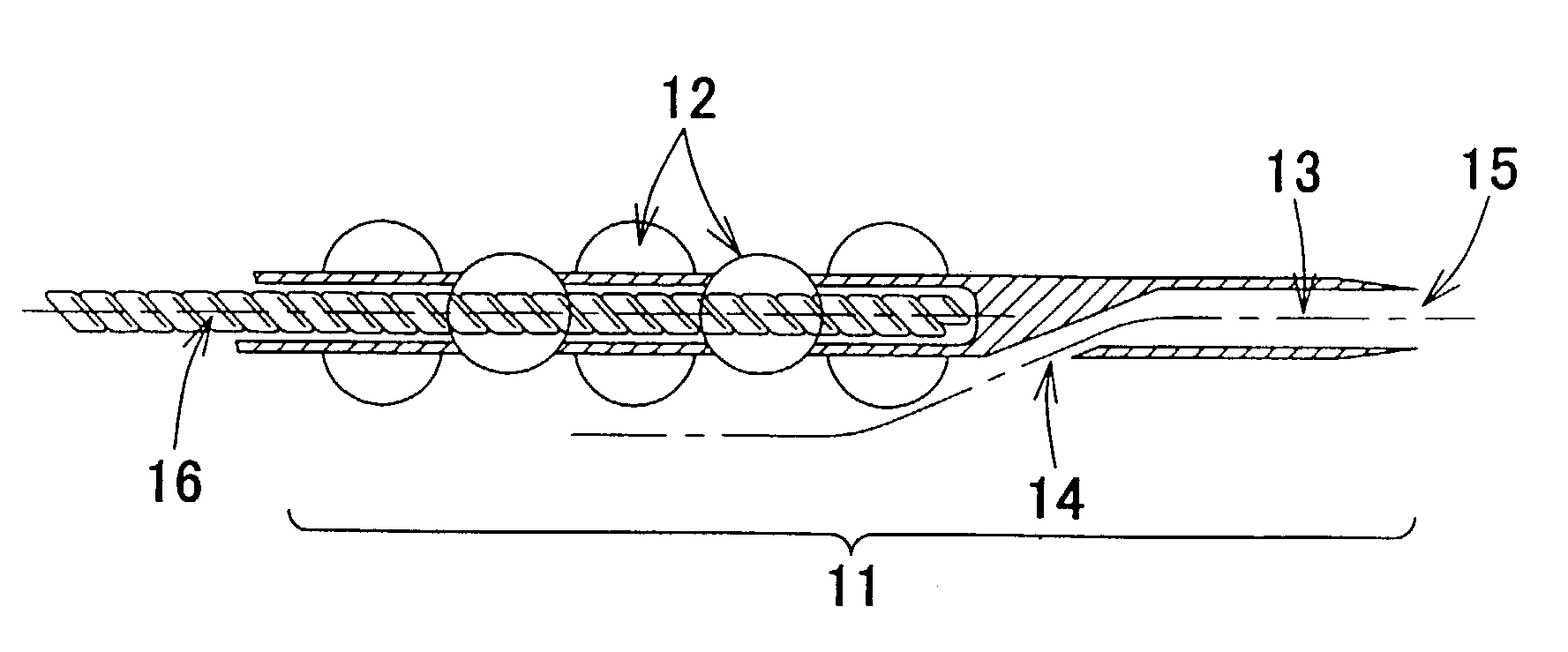
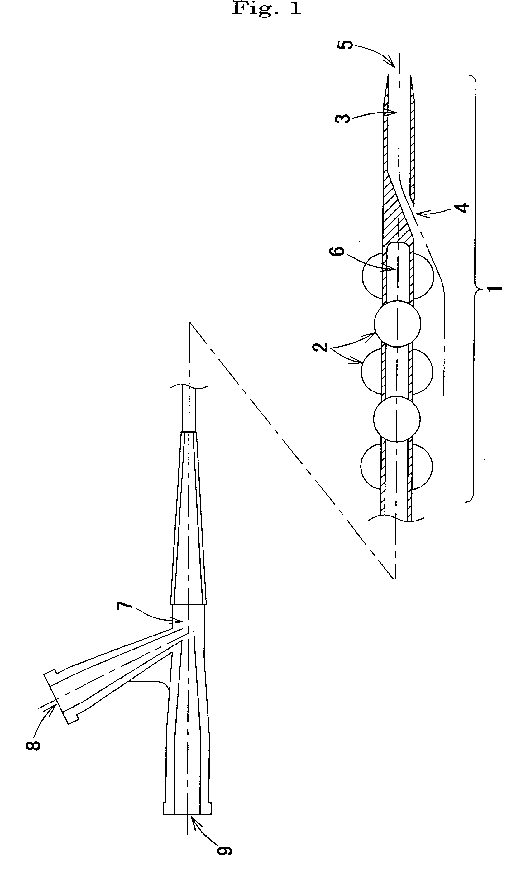
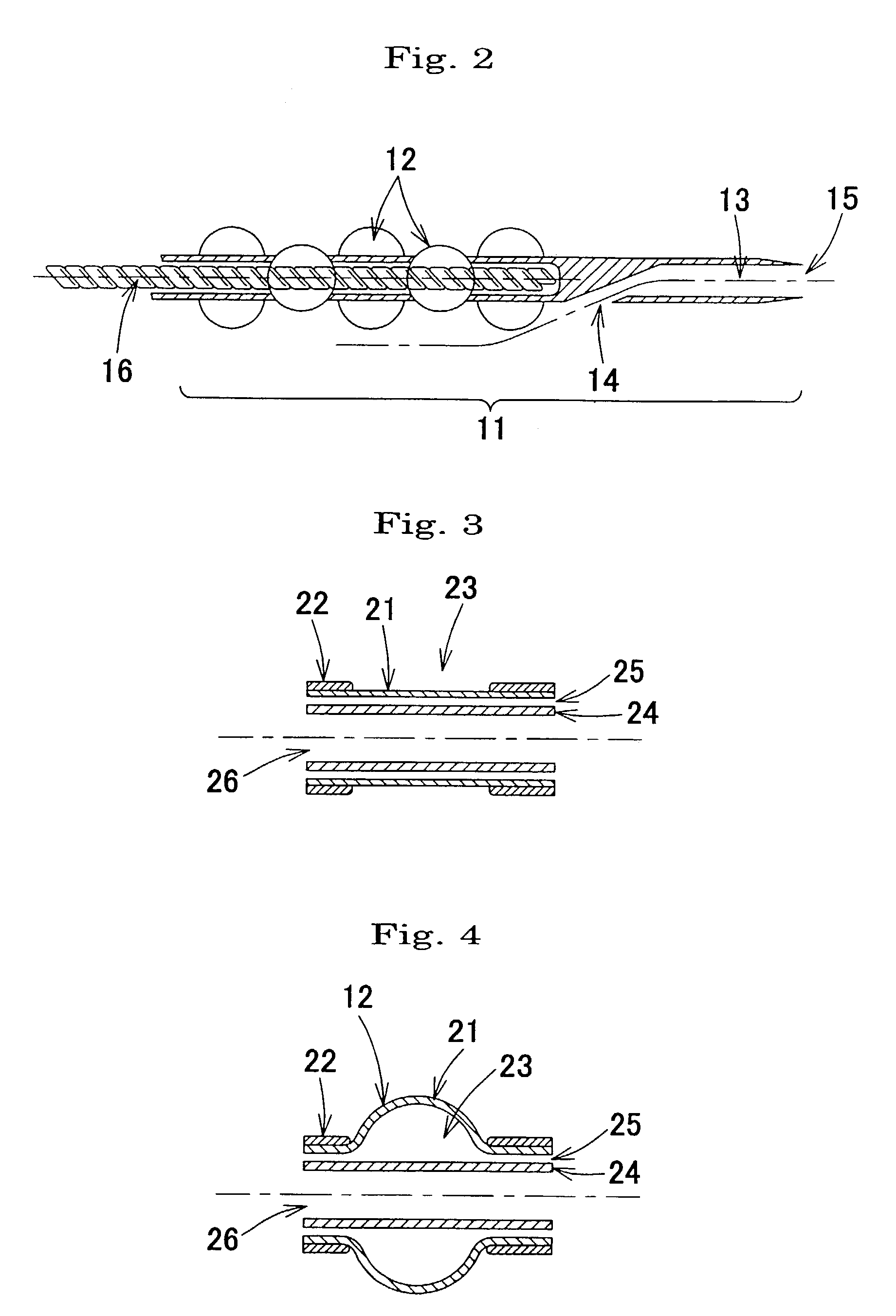
[0044]A first example of FIG. 1 is a catheter for radiation therapy for treating part of a body vessel with ionizing radiation; a state in which the expandable part has been expanded is shown. The expandable part 1 of the catheter is positioned on the tip end side of the catheter, and in the expanded state has a plurality of protruding parts 2. Specifically, when the expandable part 1 is expanded, a plurality of pairs of protruding parts 2 are produced, with the protruding parts 2 that constitute each pair being disposed so as to be produced facing in opposite directions to one another in a direction orthogonal to the axial direction of the expandable part 1, and moreover with pairs of protruding parts 2 that are adjacent to one another in the axial direction being disposed close to one another with an angle of 90° therebetween in the circumferent...


PUM

PropertyMeasurementUnit
angleaaaaaaaaaa
lengthaaaaaaaaaa
pressureaaaaaaaaaa

Abstract

In an expandable part positioned on the tip end side of the catheter, protruding parts are produced in specific regions when the expandable part is expanded through the difference in elasticity between two materials having a different elasticity to one another. The structure is made to be such that low-elasticity regions and high-elasticity regions are disposed in the expandable part, and when pressure is applied the high-elasticity regions expand more than the low-elasticity regions, thus becoming the protruding parts. Alternatively, the structure is made to be such that two materials having a different elasticity to one another are made into a two-layer structure of an inner layer and an outer layer, and voids are provided in the layer formed from the low-elasticity material, so that when pressure is applied, parts of the layer formed from the high-elasticity material corresponding to the void parts become the protruding parts.

Description

TECHNICAL FIELD[0001]The present invention relates to a catheter for radiation therapy for treating part of a body vessel with ionizing radiation.BACKGROUND ART[0002]A widely carried out therapy for stenosis of blood vessels, in particular stenosis of the coronary artery, which is a cause of myocardial infarction, angina pectoris and so on, is to expand the stenosed part using a catheter having a balloon disposed on the tip thereof, which is known as a PTCA (percutaneous transluminal coronary angioplasty) balloon catheter. Describing this technique in more detail, first a hollow φ2 mm to φ3 mm catheter called a guiding catheter for leading in the PTCA balloon catheter is led into the aorta, and the tip thereof is disposed at the entrance of the coronary artery. Next, a wire of outside diameter φ0.010″ (0.254 mm) to 0.018″ (0.457 mm) which is called a guide wire and fulfills a role of guiding the PTCA balloon catheter is led into the guiding catheter, and is passed through the stenos...

Claims


Application Information

Patent Timeline
Patent Type & Authority Patents(United States)
IPC IPC(8): A61N5/00A61M25/00A61F2/958A61L29/00A61N5/06A61N5/10
CPCA61M25/1027A61N5/1002A61M25/0054A61M25/1011A61M2025/0062A61N2005/1003A61M2025/1093A61N5/062A61M2025/1047A61M25/00
Inventor NAKANO, RYOJIISHIBASHI, TAKUYA
Owner KANEKA CORP
Why Eureka
Try Eureka