Bond coat for silicon based substrates

Active Publication Date: 2006-06-13
RAYTHEON TECH CORP
View PDF10 Cites 28 Cited by
  • Summary
  • Abstract
  • Description
  • Claims
  • Application Information

AI Technical Summary

Benefits of technology

[0007]The particular advantage achieved by the present invention is an increase in room temperature fracture toughness when compared to silicon metal bond layers as discussed above. It has been found that the fracture toughness of the bond coat is increased by more than 50% over that

Problems solved by technology

However, it has now been found that certain mechanical properties of some silicon containing substrates especially those substrates having CTE's l

Method used


Image

  • Bond coat for silicon based substrates
  • Bond coat for silicon based substrates

Examples


Embodiment Construction

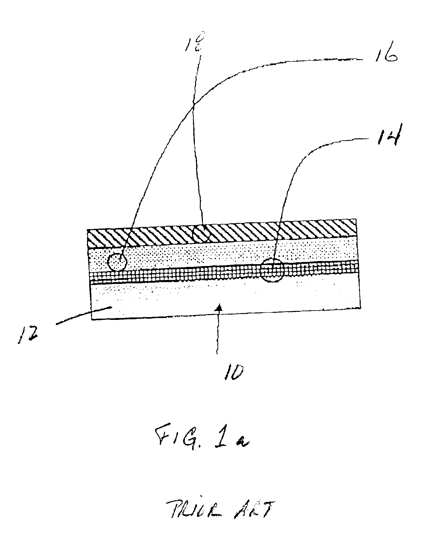
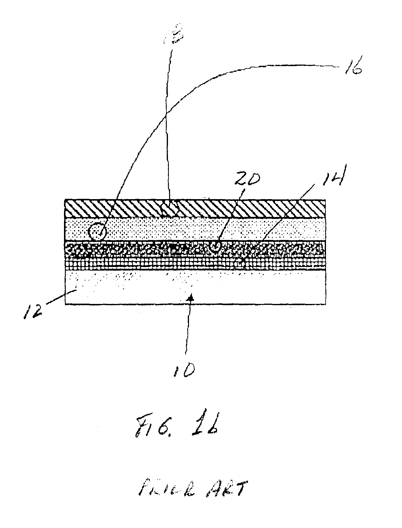
[0010]The present invention relates to an article comprising a silicon base substrate and a bond layer. The bond layer may be applied directly on the silicon base substrate or, alternatively, a silicon oxide intermediate layer or other intermediate layer may be provided between the bond layer and the silicon base substrate.

[0011]The silicon containing substrate may be a silicon ceramic substrate or a silicon containing metal alloy. In a preferred embodiment, the silicon containing substrate is a silicon containing ceramic material as, for example, silicon carbide, silicon carbide composite, silicon nitride, silicon nitride composite, silicon oxynitride and silicon aluminum oxynitride.

[0012]In accordance with the present invention, the bond layer comprises an alloy comprising a refractory metal disilicide / silicon eutectic. The bond layer may comprise 100% of the refractory metal disilicide / silicon eutectic or the bond layer may comprise a multiphase microstructure of the refractory m...


PUM

PropertyMeasurementUnit
Percent by atomaaaaaaaaaa
Melting pointaaaaaaaaaa

Abstract

A bond layer for use on a silicon based substrate. The bond layer comprises an alloy comprising a refractory metal disilicide/silicon eutectic. The refractory metal disilicide is selected from the group consisting of disilicides of molybdenum, chromium, hafnium, niobium, tantalum, rhenium, titanium, tungsten, uranium, vanadium, yttrium and mixtures thereof. The refractory metal disilicide/silicon eutectic has a melting point of greater than 1300° C.

Description

BACKGROUND OF THE INVENTION[0001]The present invention is drawn to an environmental barrier coating and, more particularly, an environmental barrier coating applied to a silicon containing substrate.[0002]Silicon based ceramics exhibit accelerated oxidation rates in high temperature, aqueous environments such as for example, the combustor and turbine sections of gas turbine engines. In order to reduce the rate of oxidation on silicon based substrates used as ceramic components in such environments, significant effort has been given to providing environment barrier coating, i.e., barrier layer(s), for the silicon based substrates so as to increase the service life of such component parts.[0003]With reference to FIGS. 1a and 1b, prior art environmental barrier coatings form a composite 10 comprising a silicon based substrate 12, a bond coat or layer 14 such as a dense continuous layer of silicon metal, a barrier layer 16 such as either an alkaline earth aluminosilicate based on barium...

Claims


Application Information

Patent Timeline
IPC IPC(8): B32B9/00F03B3/12C04B37/00C04B41/50C04B41/87C23C28/04C23C30/00F01D5/28F02C7/00
CPCC04B41/009C04B41/5071C04B41/87C23C30/00F01D5/288C04B41/5096C04B35/565C04B35/584C04B35/806C04B35/597
Inventor EATON, HARRY E.SUN, ELLEN Y.CHIN, STEPHEN
Owner RAYTHEON TECH CORP
Why Eureka
Try Eureka