Luminescent organometallic compound and light emitting device

a technology of organometallic compound and light emitting device, which is applied in the direction of discharge tube luminescnet screen, other domestic articles, natural mineral layered products, etc., can solve the problems of increasing the reliability of peripheral driving circuit, increasing the cost, and affecting the operation of peripheral electronic devices, and achieve excellent luminous efficiency

Inactive Publication Date: 2006-06-27
SANYO ELECTRIC CO LTD
View PDF7 Cites 13 Cited by
  • Summary
  • Abstract
  • Description
  • Claims
  • Application Information

AI Technical Summary

Benefits of technology

[0010]It is an object of the present invention to provide a luminescent organometallic compound having an excelle...

Problems solved by technology

Since an inorganic electroluminescent device requires high driving voltage and hence requires AC driving, it becomes difficult to increase the reliability of peripheral driving circuits and hence the cost will increase.
Furthermore, since it is driven by high AC voltage, strong electromagnetic waves are ra...

Method used


Image

  • Luminescent organometallic compound and light emitting device
  • Luminescent organometallic compound and light emitting device
  • Luminescent organometallic compound and light emitting device

Examples


example 1

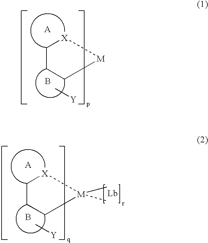
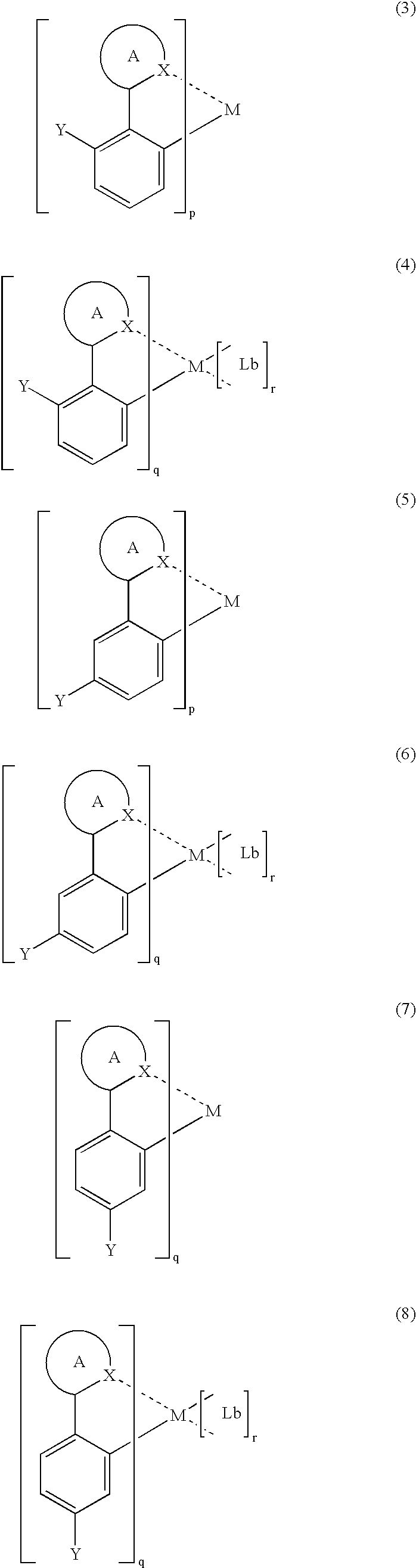
Synthesis of tris(2-(3,5-difluorophenyl-1-yl)-pyridinato-N,C2′) iridium(III)

[0068]As a reaction vessel, a four neck flask of about 500 cm3 in volume, made of borosilicate glass was prepared (hereinafter, simply referred to as a reaction vessel), and a babbled shaped Allihn type water-cooling condenser tube of which cooling part is about 20 cm long (hereinafter, simply referred to as a condenser) was connected to the reaction vessel so as to ensure airtightness at the common taper joint. A mechanic-type stirrer made up of a motor, a joint, a glass stirring bar and a stirring blades of fluorine resin, and an airtight seal through which the stirring bar is penetrated were connected to a connection port on the top of the reaction vessel, so that efficient stirring of the contents in the reaction vessel was ensured while keeping the airtightness. An enclosure-type connection tube for introducing inert gas was connected to one of connection ports on the side of the reaction vessel, making...

example 2

Synthesis of bis(2-(7-fluorobenzothiophene-2′-yl)-pyridinato-N,C2′)acetylacetonato iridium (III)

[0074]The reaction was conducted in the same manner as in Example 1 except that diethylene glycol as the reaction solvent, 1 mmol of iridium chloride (III) as the first material and 2.5 mmol of 2-(6-fluorobenzothiophene-2′-yl)pyridine as the second material were used, and an intermediate which is considered as a dinuclear complex of iridium was synthesized.

[0075]Next, the reaction was conducted in the same manner as in Example 1 except that a four neck flask of about 100 cm3 in volume as the reaction vessel, diethylene glycol as the reaction solvent, 0.1 mmol of the above-mentioned intermediate as the first material, 0.25 mmol of acetyl acetone as the ligand, 110 mg of sodium carbonate as an absorber for leaving chlorine were used, and an objective organometallic compound was obtained. This compound was irradiated with an ultraviolet ray having a wavelength of about 370 nm, and then red l...

example 3

Synthesis of tris(2-(4-fluorophenyl-1-yl)-pyridinato-N,C2′) rhenium (III)

[0076]The reaction was conducted in the same manner as in Example 1 except that 1,3-dinitrobenzene as the reaction solvent, 1 mmol of rhenium chloride (III) as the first material, (4-fluorophenyl-1-yl)-pyridine as the second material were used, and an objective organometallic compound was obtained. This compound was irradiated with an ultraviolet ray having a wavelength of about 370 nm, and then blue light emission was observed. Atomic analysis of the substance after sublimation purification resulted in a composition that almost coincides with the expected composition.


PUM

PropertyMeasurementUnit
Luminescenceaaaaaaaaaa
Chemical structureaaaaaaaaaa

Abstract

A luminescent organometallic compound having the chemical structure represented by the general formula (1) or (2):
    • [in the general formulas (1) and (2), A and B represent ring structures, M represents a metallic atom, X represents a hetero atom other than carbon and hydrogen, Y represents at least one electron-attracting group connecting to ring structure B, Lb represents a unidentate or multidentate ligand, and p, q and r represent positive integers.]

Description

BACKGROUND OF THE INVENTION[0001]1. Field of the Invention[0002]The present invention relates to an organometallic compound having an excellent luminous efficiency and capable of emitting light of spectrum components of red or blue wavelength band, and to a light emitting device such as organic electroluminescent device using the same.[0003]2. Related Art[0004]As the recent development of information technology (IT), there have been increased needs for low-profile display devices having a small thickness of about several millimeters and capable of achieving full color display. Approaches to realize the full color display can be generally classified into three types of methods: (1) arranging a number of light emitting devices which respectively emit monochromatic light of red, green and blue which are the primary colors of light; (2) using white light emitting devices in combination with color filter which allow monochromatic light of primary colors to pass through; and (3) using lig...

Claims


Application Information

Patent Timeline
IPC IPC(8): H05B33/14C07D409/00C09K11/06C07F15/00H01L51/00H01L51/30H01L51/50
CPCC07F15/0033H01L51/0085C09K11/06Y10S428/917C09K2211/1003C09K2211/1007C09K2211/1011C09K2211/1029C09K2211/1033C09K2211/1037C09K2211/1088C09K2211/185C09K2211/188H01L51/0059H01L51/0062H01L51/0081H01L51/5012H10K85/649H10K85/631H10K85/324H10K85/342H10K50/11
Inventor FUJII, HIROYUKI
Owner SANYO ELECTRIC CO LTD
Why Eureka
Try Eureka