Projection exposure method and projection exposure system

a projection exposure and projection exposure technology, applied in the field of projection exposure methods and projection exposure systems, can solve the problems of birefringent properties, limited availability, and difficulty in shortening the operating wavelength in the region below 193 nm, and achieve the effect of reducing the throughput of exposed substrates and improving image quality

Inactive Publication Date: 2006-08-15
CARL ZEISS SMT GMBH
View PDF27 Cites 102 Cited by
  • Summary
  • Abstract
  • Description
  • Claims
  • Application Information

AI Technical Summary

Benefits of technology

[0020]It has proved that incoupling of illuminating light with an incoupling intensity close to zero given numerical apertures above NA=1 begins at a working distance which corresponds approximately to four times the operating wavelength λ. It is therefore preferred when a working distance which is less than four times the operating wavelength is set, at least temporarily. In particular, the working distance should, at least temporarily, be less than approximately 50% of the operating wavelength. If working distances of 20% or less of the operating wavelength are set at least temporarily, it is possible to achieve typical incoupling levels of approximately 20% or more. A region which is useful for lithography begins with an incoupling level of approximately 20% for the photoresist materials currently available. In order to achieve higher coupling efficiencies, the working distance should be less than 10% or less than 5% of the operating wavelength for at least a portion of the exposure time. Projection objectives for the contactless near field projection lithography proposed here correspondingly preferably have typical working distances in the region of the operating wavelength or therebelow, for example between approximately 3 nm and approximately 200 nm, in particular between approximately 5 nm and approximately 100 nm. It is favourable in general when the working distance is adapted to the other properties of the projection system (properties of the projection objective near the exit surface, properties of the substrate near the incoupling surface) such that an incoupling efficiency of at least 10% is achieved. The term “incoupling efficiency” here designates the ratio of the transmission of the maximum edge or coma rays to the transmission of the chief rays during coupling out from the objective and during coupling into the resist, a mean value for various directions of polarization (s- and p-components being considered here. The incoupling is a function of the polarization and the refractive index quotients of the interface components. For apertures NA>1.0, the tangential polarization (comparable to p-polarization) supplies substantially better contrasts irrespective of whether incoupling is performed via an immersion medium or via a near field. The incoupling efficiency can fluctuate substantially depending on distance, degree of polarization and angle of incidence. The values in the following table, which specifies the incoupling efficiency as a function of the near field distance or working distance normalized to the operating wavelength can be regarded as guide values averaged over different angles of incidence, directions of polarization and mean refractive index quotients for NA>1.0.
[0026]There are a number of possibilities for actively supporting a substrate by means of controlled supporting points. One possibility consists in that, before the exposure, the surface to be exposed, for example a wafer surface, is examined for surface deformations by using appropriate measuring methods, for example interferometrically, and thereafter minimizing the surface deformation such that it is, for example, smaller than 3 nm with reference to a profile of a preferably flat desired surface. It is then possible to carry out focusing, tilting if appropriate, and exposure. Deformations before and / or during an exposure in conjunction with focusing and / or detection of the surface form are likewise possible.
[0028]Contamination problems can also be avoided or diminished by laying a transparent plane plate onto the substrate in such a way that an objective-side plane surface, averted from the substrate, of the plane plate forms the incoupling surface. The plane plate can, for example, be laid onto the substrate such that there is physical contact with the top side of the substrate at least in some regions. It is also possible for a region between the substrate-side plane surface of the plane plate and the top side of the substrate to be filled by an immersion medium, for example pure water, in part or completely. In this case, when use is made of this plane plate, which can also be designated as a plane-parallel plate or as an auxiliary plate, the small working distance, to be bridged by the near field, is formed between the objective-side plane surface of the auxiliary plate and the exit surface of the projection objective. In this variant method, the optical properties of the projection objective are coordinated with the media to be inserted between its exit surface and the substrate to be exposed such that imaging with high resolution is possible. Irrespective of whether they are provided at the objective as an exchangeable plate or as an auxiliary plate, detached from the objective, on the wafer, all the plates can be split off from a thick, plano-convex objective lens if the same or approximately the same refractive index is provided for the plate and the lens. Consequently, sufficiently thick plano-convex lenses are favourable as last lenses of the objective.
[0030]In order to avoid defocusing errors, the part of the substrate to be exposed should bear as effectively as possible against the substrate-side plane surface. If this cannot be achieved simply by laying the plane plate on, it is also possible for the substrate to be actively pressed against the substrate-side plane surface so as to produce physical contact, at least during the exposure. It is possible for this purpose, for example, to produce an overpressure, which presses the substrate against the plane plate, on the side of the substrate averted from the plane plate. It is not necessary in this case for the physical contact to be maintained over the entire substrate surface. It is sufficient if in each case the region to be exposed and, if appropriate, its adjacent regions are pressed on. It can therefore be sufficient to provide suitable outlet ducts for a pressure fluid in the region of the extension of the optical axis of the projection objective onto a substrate holder.

Problems solved by technology

The shortening of the operating wavelength λ in the region below 193 nm is rendered difficult by virtue of the fact that only a few sufficiently transparent materials, in particular fluoride crystals such as calcium fluoride or barium fluoride, are available for manufacturing lenses for this wavelength region.
These materials are available only to a limited extent and present a problem with regard to their birefringent properties at 193 nm and, in particular, at 157 nm.
However, practical systems for immersion lithography have not yet been published.

Method used


Image

  • Projection exposure method and projection exposure system
  • Projection exposure method and projection exposure system
  • Projection exposure method and projection exposure system

Examples


Embodiment Construction

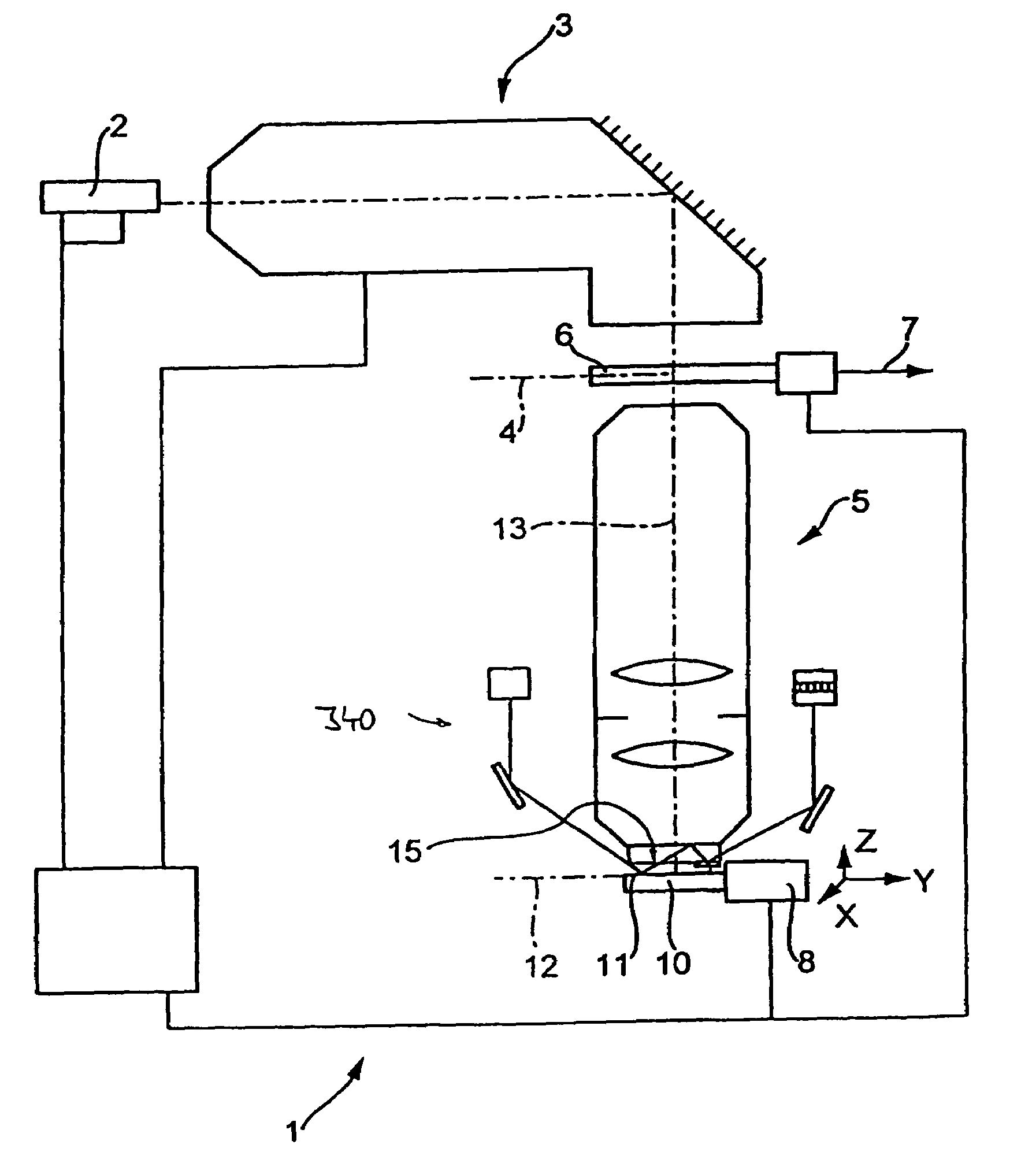
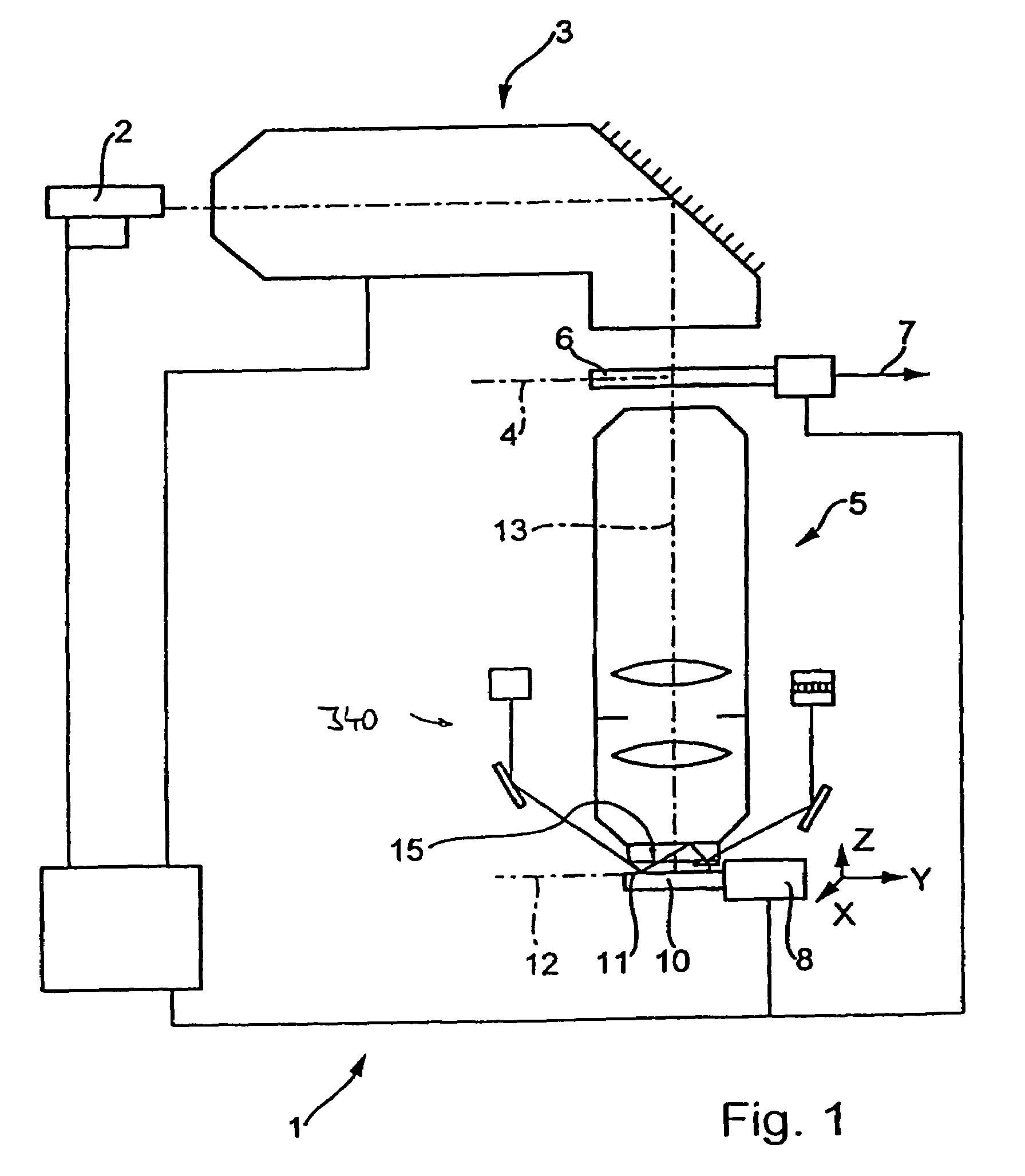
[0038]FIG. 1 shows a diagram of a microlithographic projection exposure machine in the form of a wafer stepper 1 which is provided for manufacturing highly integrated semiconductor devices. The projection exposure machine 1 comprises as light source an excimer laser 2 with an operating wavelength of 157 nm, other operating wavelengths, for example 193 nm or 248 nm also being possible. A downstream illuminating system 3 produces in its exit plane 4 a large, sharply delimited, very homogeneously illuminated image field which is adapted to the telecentric requirements of the downstream projection objective 5. The illuminating system 3 has devices for selecting the illuminating mode and in the example can be switched over between conventional illumination with a variable degree of coherence, ring-field illumination and dipole or quadrupole illumination. Arranged downstream of the illuminating system is a device for holding and manipulating a mask 6 such that the latter lies in the objec...


PUM

PropertyMeasurementUnit
operating wavelengthaaaaaaaaaa
wavelengthsaaaaaaaaaa

Abstract

In a method for manufacturing semiconductor devices and other finely structured parts, a projection objective (5) is used in order to project the image of a pattern arranged in the object plane of the projection objective onto a photosensitive substrate which is arranged in the region of the image plane (12) of the projection objective. In this case, there is set between an exit surface (15), assigned to the projection objective, for exposing light and an incoupling surface (11), assigned to the substrate, for exposing light a small finite working distance (16) which is at least temporarily smaller in size and exposure time interval than a maximum extent of an optical near field of the light emerging from the exit surface. As a result, projection objectives with very high numerical apertures in the region of NA>0.8 or more can be rendered useful for contactless projection lithography.

Description

[0001]This is a Continuation-In-Part Application of Application Ser. No. 10 / 210,051, filed Aug. 2, 2002, now U.S. Pat. No. 6,878,916 which claims benefit of the German Patent Application No. 102 29 818.1 filed on Jun. 28, 2002, and is further a Continuation-In-Part Application of International Application No. PCT / EP02 / 04846, filed on May 3, 2002, which claims benefit of the German Patent Application No. 102 10 899.4 filed on Mar. 8, 2002. The disclosures of application Ser. No. 10 / 210,051 and of application Ser. No. 10 / 379,809 filed on Mar. 6, 2003 are incorporated into this Continuation-In-Part-Application by reference. Benefit is further claimed of the German Patent Application No. 103 32 112.8 filed on Jul. 9, 2003, the disclosure of which is also incorporated by reference.BACKGROUND OF THE INVENTION[0002]1. Field of the Invention[0003]The invention relates to methods for manufacturing semiconductor devices and other finely structured components, and to projection exposure system...

Claims


Application Information

Patent Timeline
Patent Type & Authority Patents(United States)
IPC IPC(8): G03B27/42G02B7/04G03B27/52G02B7/28G02B13/14G03F7/20G03F9/00
CPCB82Y10/00G02B7/28G03F9/7026G03F7/70325G03F7/70341G02B13/14
Inventor SCHUSTER, KARL-HEINZ
Owner CARL ZEISS SMT GMBH
Why Eureka
Try Eureka