Laser welding control system

a control system and laser welding technology, applied in the field of laser welding, can solve the problems of increasing the cost and fabrication time of parts rework, the distortion of parts resulting from welding material can be unacceptably large, and the product weight is higher, so as to increase the reliability of the fabrication process and reduce the amount of rework.

Active Publication Date: 2006-09-12
ESAB AB
View PDF7 Cites 81 Cited by
  • Summary
  • Abstract
  • Description
  • Claims
  • Application Information

AI Technical Summary

Benefits of technology

[0010]For the reasons cited above, it is an object of the invention to provide a laser weld process control system for and method of fabricating structural parts that increase the reliability of the fabrication process and reduce significantly the amount of rework...

Problems solved by technology

Use of hot-rolled sections has certain inherent disadvantages with regard to product quality.
For another, the distortion on the parts resulting from working the material can be unacceptably great, which, again, requires that the part be reworked or compensatory measures taken when the hot-rolled section is assembled.
Reworking of parts increases considerably cost and fabrication time of parts.
In addition to the disadvantages mentioned above, the use of hot-rolled sections limits the designer to certain sizes and shapes, thereby resulting in a higher weight product.
The difference in dimensions most certainly adds unnecessary weight to the structure.
The use of hot-rolled structural sections also limits the types of material used.
With conventional welding systems, it is difficult to control dimensional tolerancing an...

Method used


Image

  • Laser welding control system
  • Laser welding control system
  • Laser welding control system

Examples


Embodiment Construction

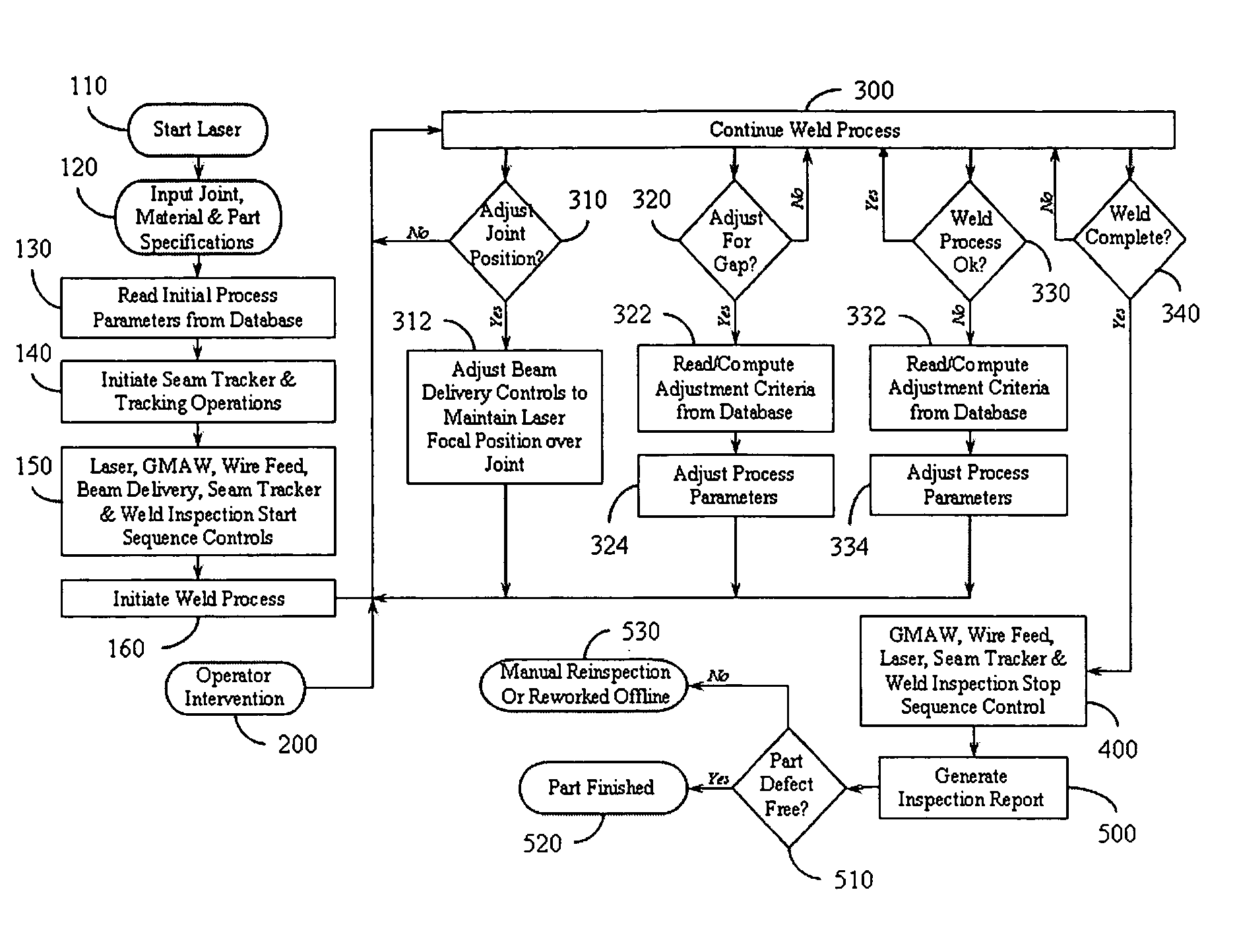
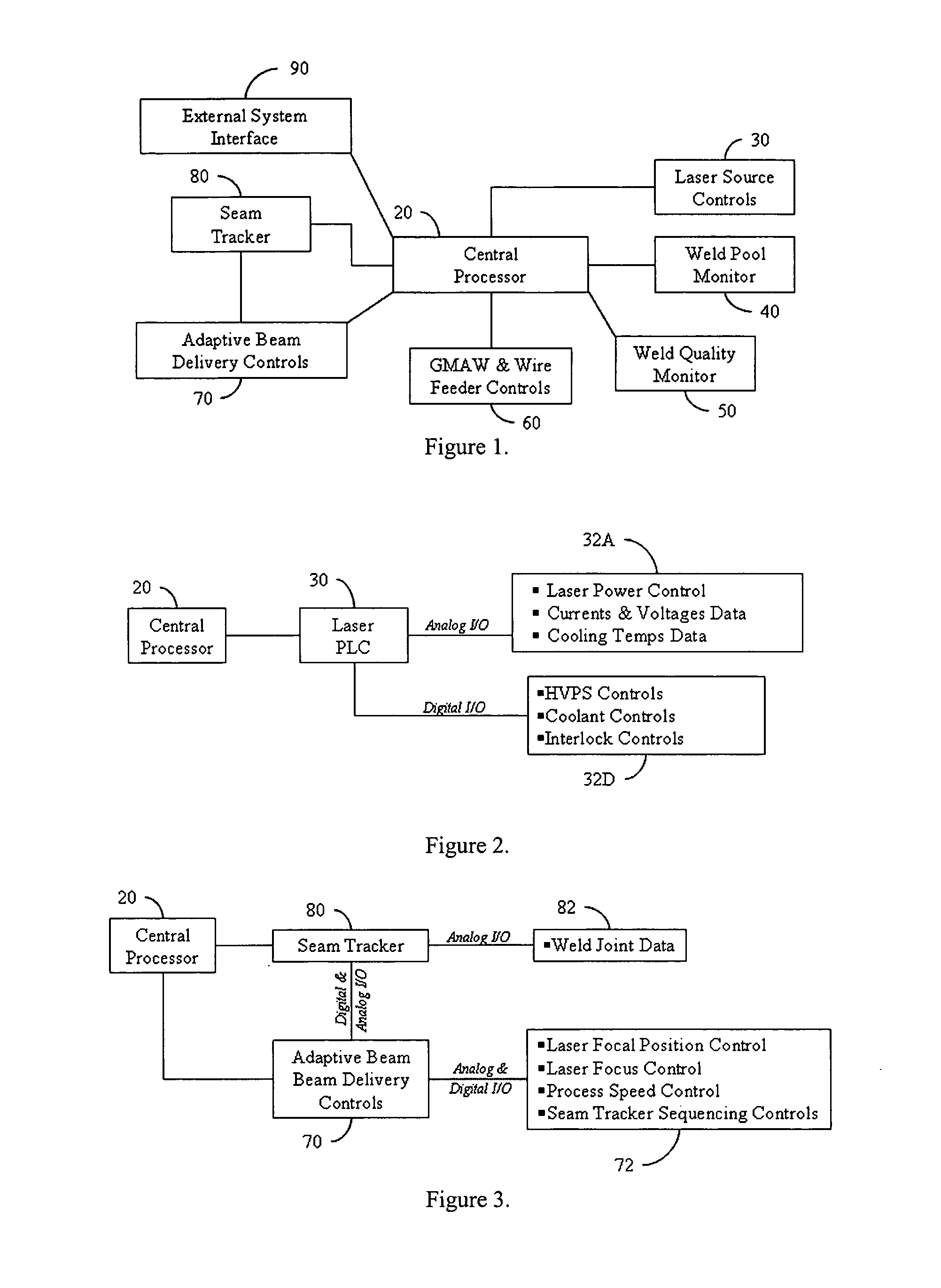
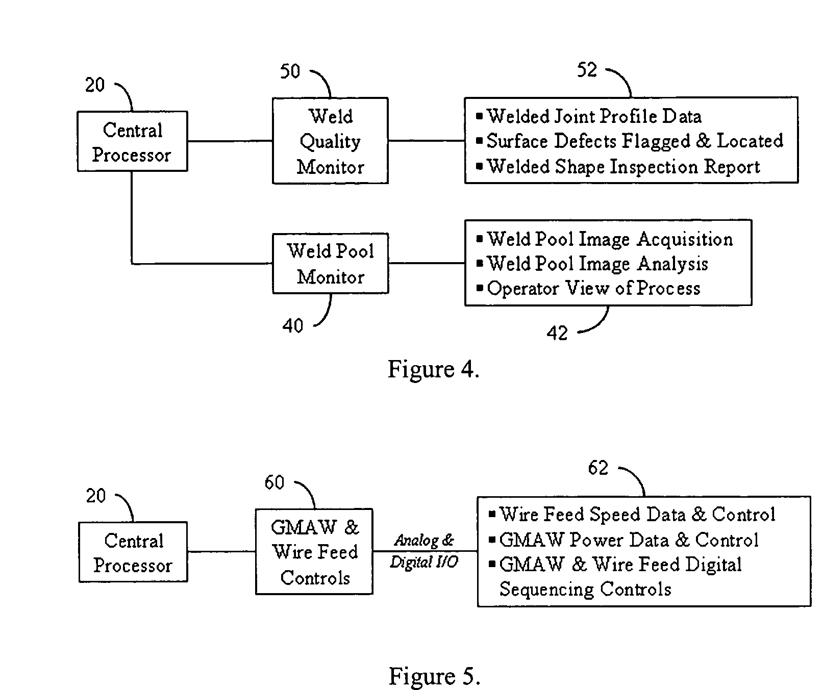
[0027]FIG. 1 is a block diagram of a laser welding control system (LWPCS) 10 according to the invention. The LWPCS 10 is a fully integrated system that comprises a central processor (CP) 20 and a plurality of subsystems. The CP 20 includes a graphical user interface (GUI) 25 and proprietary software that controls and regulates in real-time the various weld-process parameters. Included in this software is a parametric database that contains the various parameters and algorithms with which to control and / or modify the weld process. The subsystems include a laser device control subsystem (LDCS) 30, a vision-based weld pool monitoring and processing subsystem (WPMPS) 40, an active weld quality and monitoring subsystem (AWQMS) 50, a GMAW and wire feeder control subsystem (WFCS) 60, an adaptive beam delivery subsystem (ABDS) 70, and a seam tracking subsystem (STS) 80. Several of the subsystems are independently controlled by programmable logic controllers (PLCs) or by embedded processors....


PUM

PropertyMeasurementUnit
Angleaaaaaaaaaa
Sizeaaaaaaaaaa
Subsurfaceaaaaaaaaaa

Abstract

A fully integrated automated laser weld process control system (LWPCS) and method of controlling the fabrication of structural parts, particularly for shipbuilding and other industries. The LWPCS defines joint and weld quality attributes as process control variables and integrates these weld quality variables, along with the more traditional process parameters such as laser power, wire feed, GMAW voltage and active seam tracking, into a closed-loop monitoring and control system. The LWPCS includes a central processor and a plurality of subsystems that control laser beam positioning, vision-based monitoring and image processing, active weld-quality monitoring and inspection, adaptive beam delivery, and seam tracking. Cross-communication between subsystems is managed by the central processor. In addition to process control, the system extracts weld quality attributes during the weld process and provides immediate documentation of the weld quality.

Description

STATEMENT REGARDING FEDERALLY SPONSORED RESEARCH[0001]The present invention was made with Government support under Contract #: N00014-01-C-0355, awarded by the Office of Naval Research. Accordingly, the Government has certain rights in the invention.FIELD OF THE INVENTION[0002]The invention relates to the field of welding. More particularly, the invention relates to a process control system for controlling GMAW-assisted laser welding of fabricated parts.BACKGROUND INFORMATION[0003]Parts that are used on naval ships must meet high quality standards and preferably be as light in weight as possible. Certain structural shapes are typically fabricated by such methods as deflanging or splitting hot-rolled I-beams. Use of hot-rolled sections has certain inherent disadvantages with regard to product quality. For one, the tolerance range is wide, requiring that many parts fabricated from these shapes be reworked. For example, hot-rolled I-beams are often split in two to obtain T-beams. The p...

Claims


Application Information

Patent Timeline
IPC IPC(8): G06F19/00B23K26/03B23K26/20B23K31/12G05B19/401H01S
CPCB23K26/03B23K26/032B23K26/20B23K26/1429G05B19/401B23K31/125G05B2219/37217B23K26/348B23K26/242
Inventor OROZCO, NELSON J.BLOMQUIST, PAUL A.LIGHT, KENDRICK H.RUDY, ROBERT B.WEBBER, STEVEN R.
Owner ESAB AB
Why Eureka
Try Eureka