

Digital interference holographic microscope and methods
- Summary
- Abstract
- Description
- Claims
- Application Information
AI Technical Summary
Benefits of technology
Problems solved by technology
Method used
Image

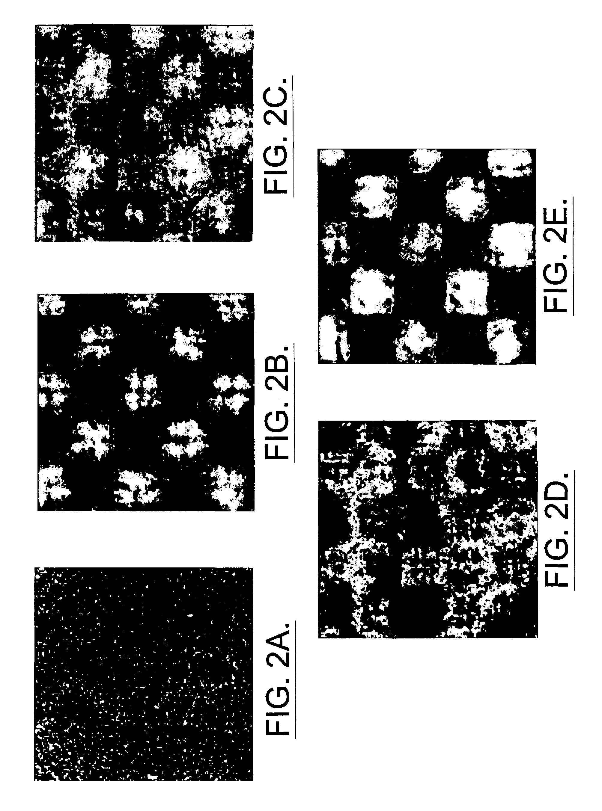
Examples
Embodiment Construction
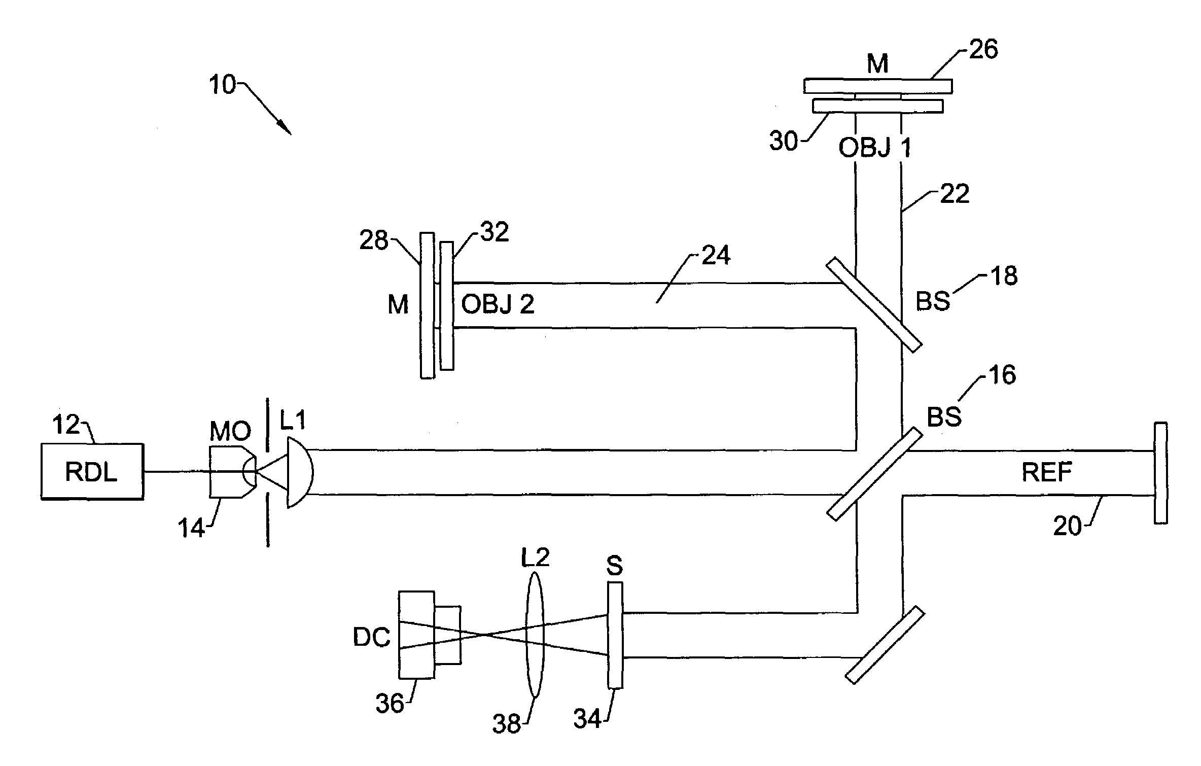
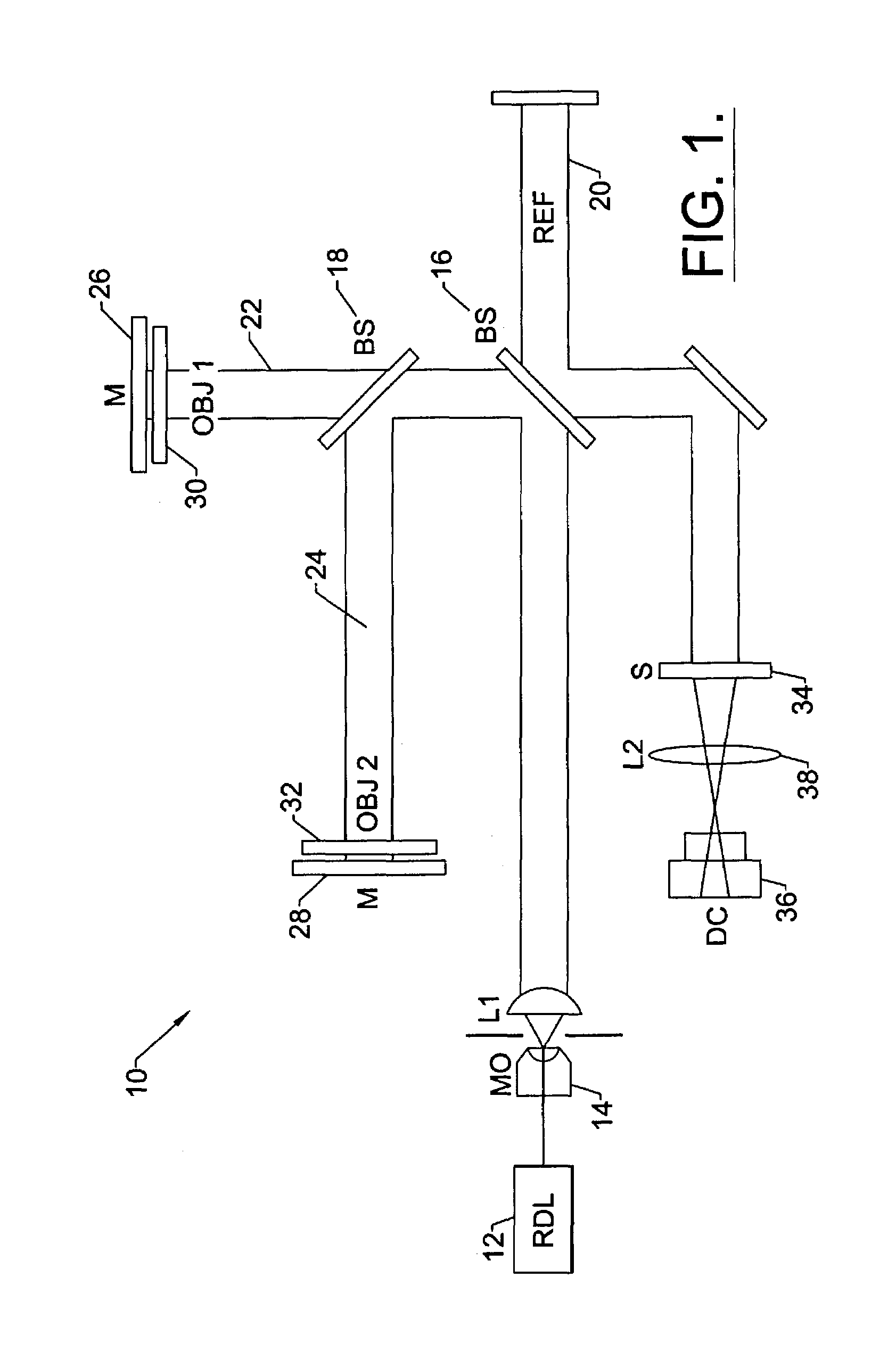
[0058]A description of the preferred embodiments of the present invention will now be presented with reference to FIGS. 1–11.
[0059]The apparatus 10 of the present invention is depicted in FIG. 1. A ring dye laser 12 provides a 595.0-nm laser field of ˜50-mW power with a linewidth of ˜50 MHz. The laser beam is expanded with a microscope objective 14 to 20 mm diameter and divided into three parts using beam splitters 16,18. One of these provides the planar reference beam 20, while the other two 22,24 constitute the object beam. The object consists of two transparency targets attached to the back-reflecting mirrors (M) 26,28 in separate optical arms, in order to avoid obstruction of one object by the other in the same optical path. One target 30 (OBJ1) is a checkerboard pattern with 2.5-mm grid size, and the other target 32 (OBJ2) is a transparent letter “A” that fits inside an opaque square of side 13 mm.
[0060]The object 22,24 and reference 20 beams are combined in a Michaelson interf...
PUM
 Abstract
Description
Claims
Application Information