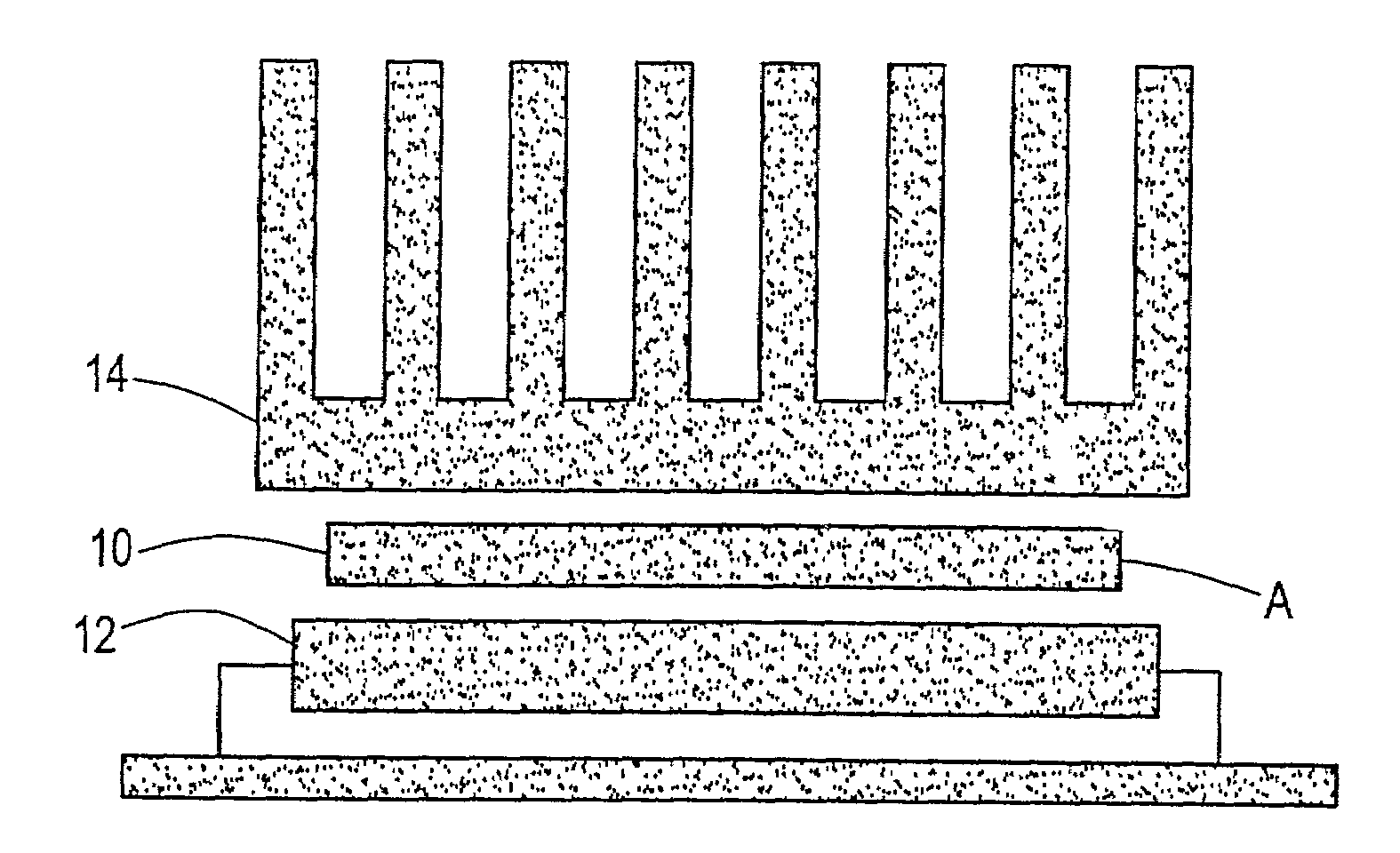
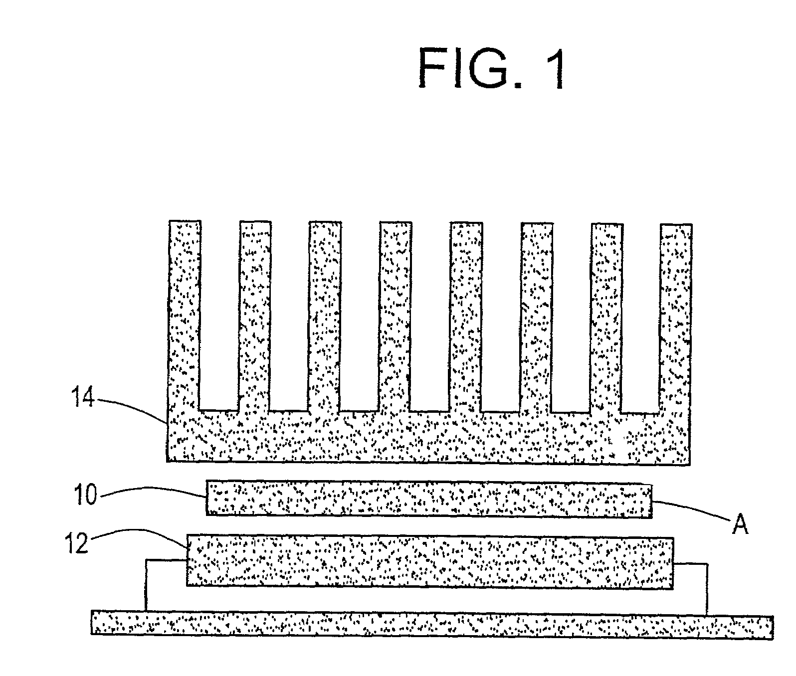
Thermal interface material with low melting alloy

a technology of thermal interface material and low melting alloy, which is applied in the direction of instruments, investigating phase/state change, and electrical apparatus casings/cabinets/drawers, etc., can solve the problems of high manufacturing cost, large heat generation of power supply assemblies of such microprocessors, and extensive assembly process. , to achieve the effect of easy field service, equivalent thermal performance and convenient handling

Inactive Publication Date: 2006-12-12
SAINT GOBAIN PERFORMANCE PLASTICS CORP
View PDF84 Cites 81 Cited by
  • Summary
  • Abstract
  • Description
  • Claims
  • Application Information

AI Technical Summary

Benefits of technology

[0021]Another advantage of at least one embodiment of the present invention is that the cohesive strength and integrity of the thermal interface material provide for easy handling.
[0022]Still another advantage of at least one embodiment of the present invention is that the thermal performance of the thermal interface material matches or exceeds that of thermal grease in a solid film form.
[0023]Still another advantage of at least one embodiment of the present invention is that the assembly process associated with thermal grease is eliminated but an equivalent t

Problems solved by technology

Power supply assemblies for such microprocessors generate considerable heat during operation.
If the heat is not adequately removed, the increased temperatures generated by the power supply assemblies will result in damage to the semiconductor components.
Thermal greases provide excellent thermal properties, but require an extensive assembly process with high manufacturing cost.
This process is labor intensive and slow and does not lend itself to automation.
These compounds, however, are generally brittle at ambient temperatures and easily chipped off, resulting in a high thermal resistance.
Further, because of the brittle nature of the wax compounds, they are difficult to manufacture and apply to a heat sink.
Although soft and pliable, the silicone rubber requires relatively high pressure and a long warm-up time to atta

Method used


Image

  • Thermal interface material with low melting alloy
  • Thermal interface material with low melting alloy

Examples


example 1

[0074

A thermal transfer composition was prepared by forming a matrix an incorporating an LMA into the matrix. The following components were melted together to form the matrix:

[0075]1 part by weight Kraton 1652

[0076]2 parts by weight Regalite

[0077]3 parts by weight Shellflex

[0078]0.05 parts by weight antioxidant.

[0079]The melted matrix was a clear fluid liquid which, if cooled, becomes a solid pressure sensitive adhesive. The polymer matrix was combined with an LMA in the ratio of 1 part by weight polymer matrix to 9 parts by weight LMA at a temperature above the melting point of the LMA (i.e., above 60°C.). The LMA was an alloy comprising 32.5% bismuth, 16.5% tin, and 61.0% indium, having a melting point of 60° C.

[0080]With stirring the melt became dark gray as the silvery LMA is incorporated into the polymer melt. The mixture of matrix and LMA was removed from the heat source and stirred as it cooled. When the mixture temperature is below the melt point of the LMA the dispersion is...

example 2

[0081

A matrix was formed by melting together:

[0082]1 part by weight Kraton 1652[0083]2 parts by weight Regalite 1100 resin[0084]3 parts by weight Shellflex Oil 371[0085]0.05 parts by weight Irganox 1010 (antioxidant)[0086]0.05 parts by weight TTS Titanate (a wetting and flux agent)

[0087]The melted matrix was combined with the LMA of Example 1 in the ratio of 1 part matrix to 9 parts LMA at a temperature above the melting point of the LMA (i.e., above 60°C.).

[0088]The mixture of matrix and LMA was removed from the heat source and stirred as it cooled. When the mixture temperature is below the melt point of the LMA the dispersion is stable.

[0089]The cooled dispersion was converted into a thin film suitable for use as a thermal interface materials by calendaring, dissolving and coating onto a release liner. When used at a thickness of approximately 0.1 mm in a pentium emulator gave a ΔT of 5°C. ΔT is defined as Tj-Ts, where Tj is the junction temperature of the microprocessor and Ts is...

example 3

[0090

A polymer matrix was formed as for Example 2 but with the addition of 9 parts by weight of zinc oxide (ZnO).

[0091]The melted matrix and ZnO was a white liquid which, if cooled, becomes a solid pressure sensitive adhesive.

[0092]The melted matrix with ZnO was combined with the LMA of Example 1 in the ratio of 1 part of polymer matrix plus ZnO to 2 parts LMA at a temperature above the melting point of the LMA. With stirring, the melt became light gray as the silvery LMA was incorporated into the polymer melt.

[0093]The mixture was removed from the heat source and stirred as it cooled. When the mixture temperature is below the melt point of the LMA the dispersion is stable.

[0094]The cooled dispersion was converted into a thin film suitable for use as a thermal interface material by calendaring, dissolving, and coating on a release liner.

[0095]When the interface material was used a thickness of approximately 0.1 mm in a pentium emulator gave a ΔT of 4° C. The addition of ZnO gave an ...


PUM


Abstract

A thermal interface composition undergoes a viscoelastic change at microprocessor operating temperatures to transfer heat generated by a heat source, such as a microprocessor to a heat sink. The composition includes a low melting alloy dispersed in a matrix. The matrix comprises a viscoelastic composition which softens at about the operating temperature of the heat source. The viscoelastic composition may include a thermoplastic elastomer, a compatible hydrocarbon oil, and a tackifying resin. In use, the thermal interface composition flows under pressure between the heat source and the heat sink to make thermal contact between the two. When the heat source is operated and reaches operating temperature, the viscoelastic composition softens and the low melting alloy melts at around the operating temperature to form a highly thermally conductive, generally homogeneous mixture which readily transfers heat to the heat sink.

Description

FIELD OF THE INVENTION[0001]The present invention relates to thermally conductive materials, and more particularly, to a thermally conductive interface material comprising a low melting point alloy (LMA) that facilitates heat transfer from the heat generating device to a heat sink. The interface material finds particular application in heat generating devices, such as microprocessor power supply assemblies, and the like, although it will be appreciated that the material has a variety of other applications.BACKGROUND OF THE INVENTION[0002]With increasing market pressure for smaller, faster and more sophisticated end products using integrated circuits, the electronics industry has responded by developing integrated circuits which occupy less volume, yet operate at high current densities. Power supply assemblies for such microprocessors generate considerable heat during operation. If the heat is not adequately removed, the increased temperatures generated by the power supply assemblies...

Claims


Application Information

Patent Timeline
IPC IPC(8): G01N25/04G01K1/12H01L23/373H01L23/42H01L23/427
CPCH01L23/3736H01L23/3737H01L23/42H01L23/4275Y10T428/2852H01L2924/0002H01L2924/00
Inventor BALIAN, CHARLESBERGERSON, STEVEN E.CURRIER, GREGG C.
Owner SAINT GOBAIN PERFORMANCE PLASTICS CORP
Why Eureka
Try Eureka