Microfabricated microconcentrator for sensors and gas chromatography

Inactive Publication Date: 2006-12-12
NEW JERSEY INSTITUTE OF TECHNOLOGY
View PDF30 Cites 49 Cited by
  • Summary
  • Abstract
  • Description
  • Claims
  • Application Information

AI Technical Summary

Benefits of technology

[0012]The present invention provides a device for enhancing the sensitivity of a microsensor (or any other micro device) by providing on-line preconcentration. The invention provides a micromachined concentrator (hereinafter referred to as the microconcentrator) on a silicon substrate, that can be integrated with a sensor or a micromachined GC to enhance the signal to noise ratio. The present invention comprises a microconcentrator comprising a miniaturized sorbent trap fabricated on a microchip. In a preferred embodiment the microconcentrator is made on a silicon substrate so that a sensor or micromachined GC can be integrated on the same chip. In accordance with the invention, in pr

Problems solved by technology

Environmental monitoring requires the measurements of pollutants at trace concentrations (ppm to ppt), because even at these levels they pose a threat to human health and to the environment.
However, they are relatively large, expensive and do not lend themselves to easy portability.
The limited success of microsensors are due to the

Method used


Image

  • Microfabricated microconcentrator for sensors and gas chromatography
  • Microfabricated microconcentrator for sensors and gas chromatography
  • Microfabricated microconcentrator for sensors and gas chromatography

Examples


experiment 1

[0048]Now referring to FIG. 5, a microconcentrator 2 in accordance with the present invention was employed in conjunction with a pulse heater 65, a conventional flame ionization detector (FID) 70, in this case a SRI Instrument Model 8600 / 9300 portable GC equipped with a FID and a computer 80 for data acquisition. The microconcentrator 2 was cooled by placing it over an ice pack. A commercially available capillary column such as a 0.53 mm ID, 30 m long capillary column (DB-624,J&W Scientific) was employed in some tests. Repeat injections were made under isothermal conditions to generate a series of chromatograms. Standard gases such as air, nitrogen, and hydrogen were purchased from Matheson Gas Co., NJ. Nitrogen was used as the carrier gas, and the flow rate was 7 ml / min. Data acquisition was carried out using the Peaksimple Data System supplied by SRI Instruments. Calibration, qualitative / quantitative analysis, documentation of analytical results, and report output were handled by ...

experiment 2

oconcentrator

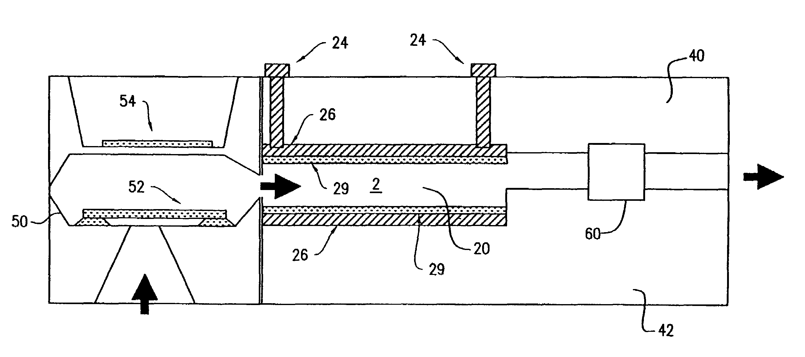
[0051]Now referring to FIG. 7, a microconcentrator according to the present invention was put on-line with the sample stream. The gaseous sample containing the analyte was introduced into the detector through the microconcentrator. The analytes were trapped in the polymer film 29 and could be thermally desorbed by electrical heating. The desorption was achieved by resistive heating by a current pulse (1 to 3 sec.). Rapid desorption was essential for producing a sharp concentration pulse to provide high throughput in terms of mass of sample per second. The mode of operation for continuous monitoring was that electrical pulses (injections “I”) were made at fixed intervals of time, and corresponding to each injection, a signal pulse (“C”) was obtained. Continuous monitoring using the microconcentrator 2 was demonstrated by monitoring a stream of organic vapors. As seen in FIG. 7, the microconcentrator 2 generated a series of signal pulses corresponding to a sequence of inj...

experiment 3

[0054]Now referring to FIG. 9, the microconcentrator 2 response as a function of injection interval was studied at 0 and 25 C using toluene as the analyte. As the interval increased, the amount of sample trapped in the microconcentrator 2 increased. However, once the interval equaled tb, the sample began to breakthrough, and the response could not be increased further. The response profile showed a linear increase in response up to tb, followed by a constant response beyond tb. It was seen that the temperature affected microconcentrator 2 operations; lower temperature increase tb.

[0055]Linearity in microconcentrator response was observed as a function of concentration. The concentration range studied here was from 20 to 800 ppm of toluene. Since the amount of sample trapped in the microconcentrator was proportional to the concentration of the stream flowing in, its response was proportional to sample concentration. At a longer injection interval, the larger amount of trapped sample ...


PUM

PropertyMeasurementUnit
Ratioaaaaaaaaaa
Sensitivityaaaaaaaaaa

Abstract

Devices for enhancing the sensitivity of a microsensor or any other micro device by providing on-line preconcentration. Microconcentrators that can be integrated with a sensor or a micromachined GC to enhance the signal to noise ratio can include a miniaturized sorbent trap fabricated on a microchip. The microconcentrator can be made on a silicon substrate so that a sensor can be integrated on the same chip. The microconcentrator is composed of at least one microchannel lined with a microheater for in-situ heating. Preconcentration may be achieved on a thin-film polymeric layer deposited above the heater in the microchannel. Rapid heating by the channel heater generates a “desorption pulse” to be injected into a detector or a sensor.

Description

RELATED APPLICATIONS[0001]This application claims the benefit of U.S. Provisional Application No. 60 / 433,475, filed Dec. 13, 2002, entitled “Microfabricated Microconcentrator for Sensor and Chromatography,” the entirety of which is incorporated herein by reference.FIELD OF THE INVENTION[0002]The present invention relates to microconcentrators, specifically, microconcentrators for devices such as sensors and gas chromatographs.BACKGROUND OF THE INVENTION[0003]Environmental monitoring requires the measurements of pollutants at trace concentrations (ppm to ppt), because even at these levels they pose a threat to human health and to the environment. A variety of conventional laboratory based analytical techniques are used for pollution monitoring. Currently, gas chromatographs, mass spectrometers and Fourier transform infrared spectrometers (FTIR) are the most commonly used instruments. These techniques have excellent merits in terms of sensitivity, detection limit and other performance...

Claims


Application Information

Patent Timeline
IPC IPC(8): B01D53/04G01N1/40G01N30/02G01N30/12G01N30/60G01N30/62
CPCG01N30/12G01N30/6095G01N2030/025G01N2030/121G01N2030/623G01N1/40
Inventor MITRA, SOMENATH
Owner NEW JERSEY INSTITUTE OF TECHNOLOGY
Why Eureka
Try Eureka