Flow-through optical assay devices providing laminar flow of fluid samples, and methods of construction thereof

a flow-through optical assay and fluid sample technology, applied in the direction of biomass after-treatment, analysis using chemical indicators, instruments, etc., can solve the problems of not offering the desired channel flow characteristics or optical properties, and achieve the effect of reducing the assay performance time, increasing analytical sensitivity, and improving sensitivity

Inactive Publication Date: 2006-12-26
INVERNESS MEDICAL - BIOSTAR
View PDF44 Cites 26 Cited by
  • Summary
  • Abstract
  • Description
  • Claims
  • Application Information

AI Technical Summary

Benefits of technology

[0068]One advantage of the present invention is an enhanced sensitivity due to an increase in the available or useable sample volume which is brought in contact with the analyte specific receptive material by the mass transport / laminar flow effect. This system can provide an increase in analytical sensitivity of at least 40 fold.
[0069]A second advantage is the reduction of the assay performance time. The incubation times are decreased by delivering new analyte to the surface through fluid mass transport / laminar flow which does not occur in simple diffusion. The time per step basis is reduced from the minute time scale to the seconds time scale due to efficient delivery of material to the surface by mass transport / laminar flow and increasing the sample volume applied to the surface. The increased sensitivity and speed will be especially useful for the detection of analytes such as antigens or DNA in samples.
[0070]A third advantage is that the incubation time can be controlled by the wicking rate, differential pressure, channel size, and sample viscosity, rather than manually timing each step. All subsequent surface incubation times may be of a similar time frame. Another possibility is to use layers of wicking materials with different capillary rates, wetability rates, or flow characteristics to control incubation times.
[0071]A fourth advantage is ease of manufacturing. The materials which are useful as layers of the devices are compatible with continuous on line web processing. All optical processing can be done in one step or one continuous operation. There is also an economy of scale as large sheets of materials can be processed. In addition, the yield for any one step is improved over that of manufacturing discrete components of a device. Furthermore, attachment layers (e.g., Ni, diamond-like carbon) can be applied while processing the optical layers. Also, use of these materials allows for flexible optical design, as the optical layers can be readily interchanged and additional layers of materials (e.g., AR, receptive layer) can be easily added.
[0072]A fifth, the advantage of using a device which utilizes mass transport / laminar flow characteristics in an automated system is that samples may flow through the surface eliminating the need for vacuum and pressure rinsing which creates aerosols and makes containment difficult.
[0073]The methods and devices of the present invention are distinct from the prior analytical methods which all rely on the adhesion or capture of an analyte specific reagent within the numerous pores or fibers within the membrane or filter material. In these methods, such membrane or filter material is used to contain the specific binding reagent, separate the unreacted sample material from the bound analyte and increase the surface area available for binding reagent. The binding reagent is found on the surface and within the pores and detection can occur to some depth within the porous material dependent on the signal generation method used. These materials employ overall porosities of 60%. The pore sizes of these materials are on the order of 0.45 microns. The pores or networked surfaces are highly complex and interconnected. This introduces a plug flow type of system. In distinction, in the present invention the channels do not exceed 15% of the total surface area of any layer and are discrete with no interconnections producing a flow that is laminar in character. A further distinction is that binding of analyte within the pores or channels is insignificant and does not contribute to the generation of detectable signal.

Problems solved by technology

The porous support while open to fluid flow, does not offer the desired channel flow characteristics or optical properties.

Method used


Image

  • Flow-through optical assay devices providing laminar flow of fluid samples, and methods of construction thereof
  • Flow-through optical assay devices providing laminar flow of fluid samples, and methods of construction thereof
  • Flow-through optical assay devices providing laminar flow of fluid samples, and methods of construction thereof

Examples


example 1

Use of Absorbent Material to Evaluate Flow Characteristics

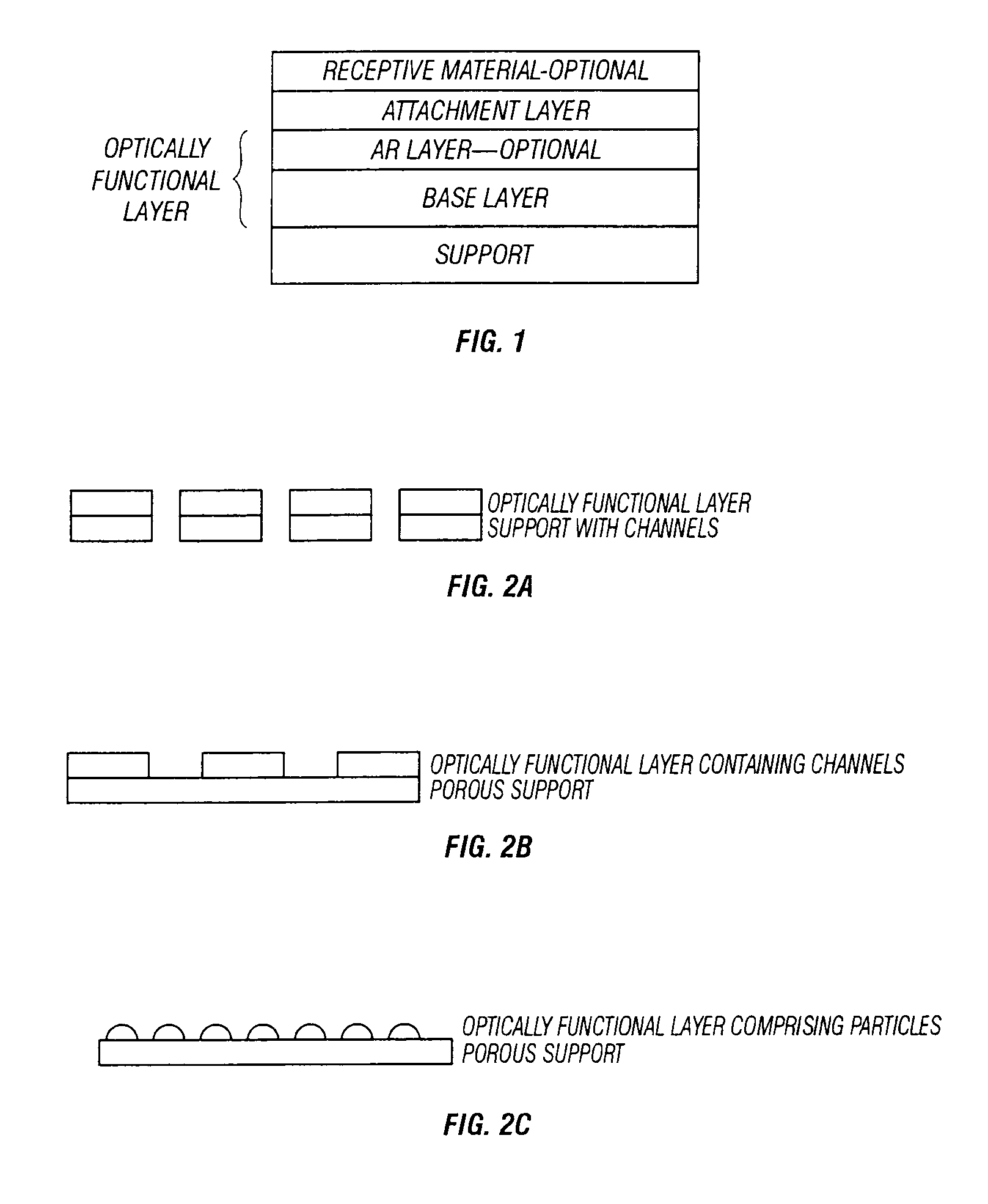
[0132]The flow characteristics of the 0.6, 1, and 5 μm channeled-polycarbonate supports show the desired flow characteristics when backed with cellulose acetate or other fibrous or porous wicking material. Flow characteristics of interest are the flow rate through and / or across the surface, the retention of fluid at the optical surface, and uniform flow of sample solution over entire surface. The flow rate should be selected to allow sufficient reaction time assuming that 160 to 1000 μl of sample will be used. Optimal flow and drying of the surfaces are achieved when the hydrophilic channeled supports are backed with a very thin hydrophobic membrane which is backed with another hydrophilic absorbent material to prevent backflow of the sample as the surface dries. The drying step, while not a necessary step in visualization of the optical signal does produce a signal that is more easily assessed due the lower index of air comp...

example 2

Assay Time Reduction Relative to a Non-Channeled Support

[0133]Test surfaces reactive to the polysaccharide antigen specific to group A streptococcus were produced on a non-channeled support (silicon) and a channeled support (polycarbonate). The silicon test device is a commercially available device. The channeled support was a 1 μm channel size polycarbonate which was coated with amorphous silicon followed by silicon nitride and then silylated with DCDMS as in Example 3. Once silylated, the surface was coated with anti-Strep A antibody and modified STREP A OIA® assays were carried out. Antigen was extracted in a 1 minute extraction step. The extraction was neutralized with a reagent which also contains the conjugated anti-Strep A antibody with HRP for precipitation of a solid film forming enzyme product. The complete extraction volume 250 μl (but can be in excess of 300 μl) was applied to the surface of the channeled device. Sample size for the solid non-channeled device is limited ...

example 3

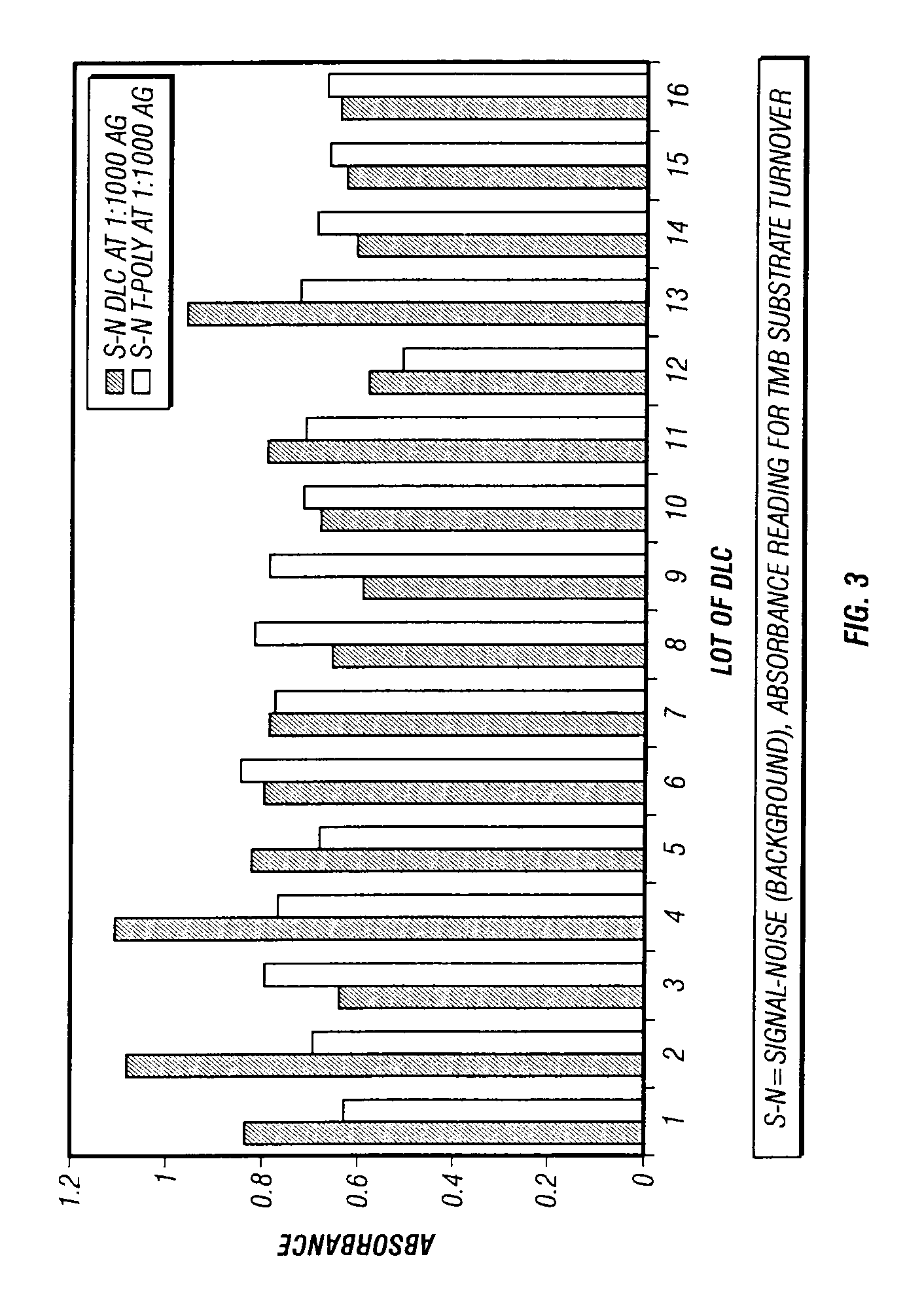
Strep A OIA® Assay Comparison

[0134]A support of polycarbonate with 1 μm channels was coated with a base optical layer of amorphous silicon to a thickness of 2000 Å. The AR layer was silicon nitride coated to a thickness of 420 Å, refractive index is 2.0. The optical layers were applied by ion beam deposition using industry standard parameters. The attachment layer was DCDMS, 2% in 1,1,1-Trichloroethane which was coated onto the essentially support using a vapor deposition method with no catalyst and for 10 minutes at room temperature. Anti-Strep A antibody was applied by solution coating the device for 2 hours at 45° C. in a solution containing 0.1 M HEPES, pH8.0, 6 μg / ml of antibody. The device was rinsed with deionized water and used immediately. The assay of this device used 360 μl of pre-extracted antigen standard+40 μl of conjugate. The mixture was applied to the optical device and differential pressure (vacuum) applied for 2 minutes for each antigen standard and then 2 washes ...


PUM

PropertyMeasurementUnit
sizeaaaaaaaaaa
porositiesaaaaaaaaaa
pore sizesaaaaaaaaaa

Abstract

An optical assay device for the detection of an analyte of interest in a sample comprising a support containing channels, an optically functional layer positioned on the support such that the optically functional layer and the support allow for laminar flow of the sample through layers of the device, an attachment layer positioned on the optically functional layer, and an analyte specific receptive layer positioned on the attachment layer.

Description

[0001]This application is a continuation-in-part of U.S. Ser. No. 08 / 742,755 filed Oct. 31, 1996, now abandoned, which is hereby incorporated by reference herein, including all tables, figures, and claims.BACKGROUND OF THE INVENTION[0002]The present invention relates to methods and devices useful for analytical testing. Such testing includes, but is not limited to medical diagnosis and environmental testing.[0003]The following is a discussion of relevant art, none of which is admitted to be prior art to the present invention.[0004]A flow-through, or porous, assay device is described in U.S. Pat. No. 4,632,901 by Valkirs, et al. In this method an immunoassay is performed on a membrane or filter which is coated with an antibody and is capable of removing an analyte from a sample applied to the membrane. Visualization is based on the analyte dependent capture of a secondary reagent which will act on a substrate and produce a colored, particulate product which will non-specifically adhe...

Claims


Application Information

Patent Timeline
Patent Type & Authority Patents(United States)
IPC IPC(8): C12Q1/68C12M1/00G01N15/06G01N31/22G01N21/27G01N21/77G01N33/543G01N33/553
CPCG01N21/7703G01N33/54373C12Q1/68
Inventor DREWES, JOEL A.BOGART, GREGORY R.ETTER, JEFFREY B.STEAFFENS, JEFFREY W.OSTROFF, RACHEL M.CROSBY, MARK
Owner INVERNESS MEDICAL - BIOSTAR
Why Eureka
Try Eureka