
Microarrays on mirrored substrates for performing proteomic analyses

Inactive Publication Date: 2006-12-26
CHIRON CORP
View PDF35 Cites 26 Cited by
  • Summary
  • Abstract
  • Description
  • Claims
  • Application Information

AI Technical Summary

Benefits of technology

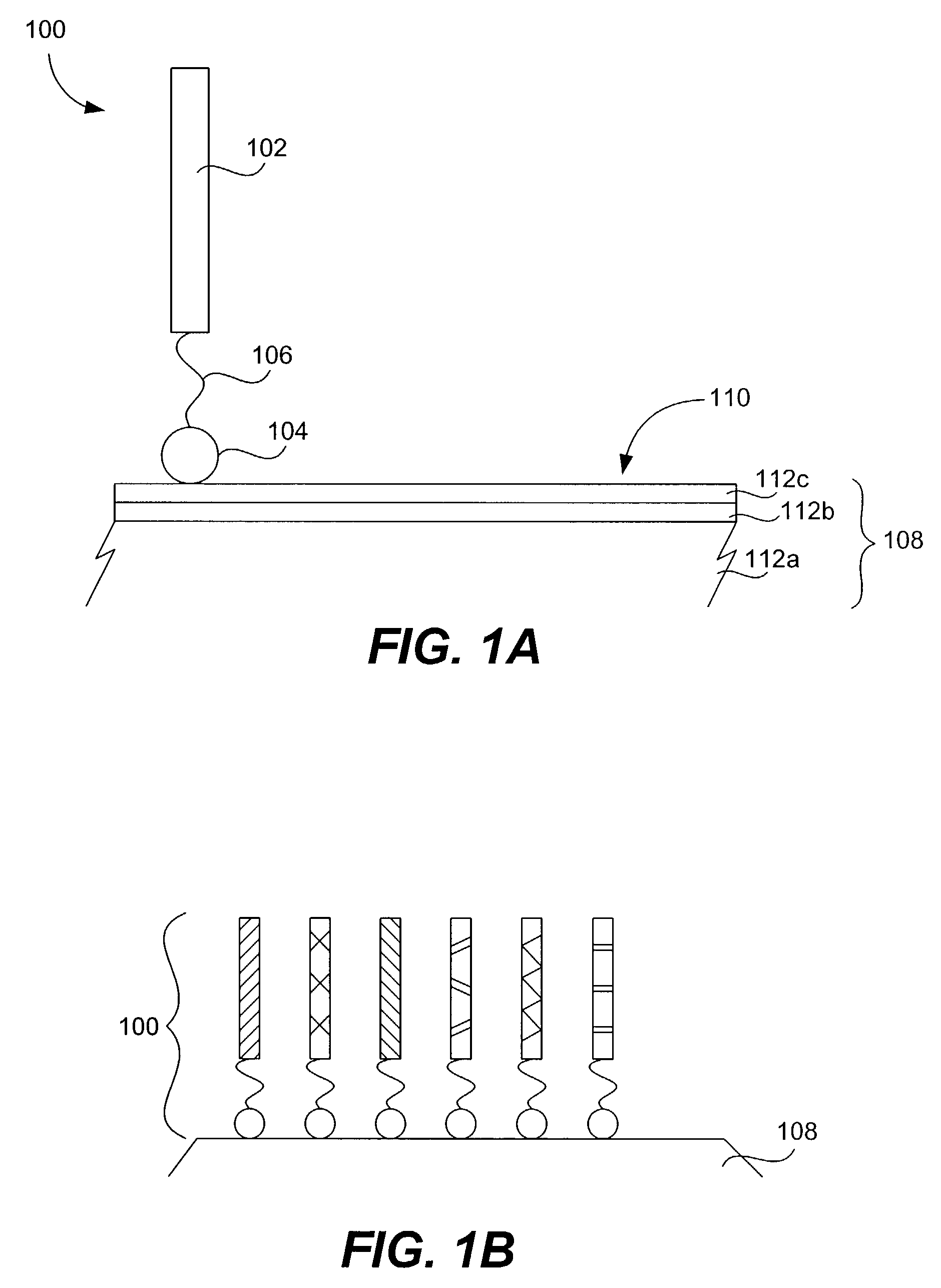
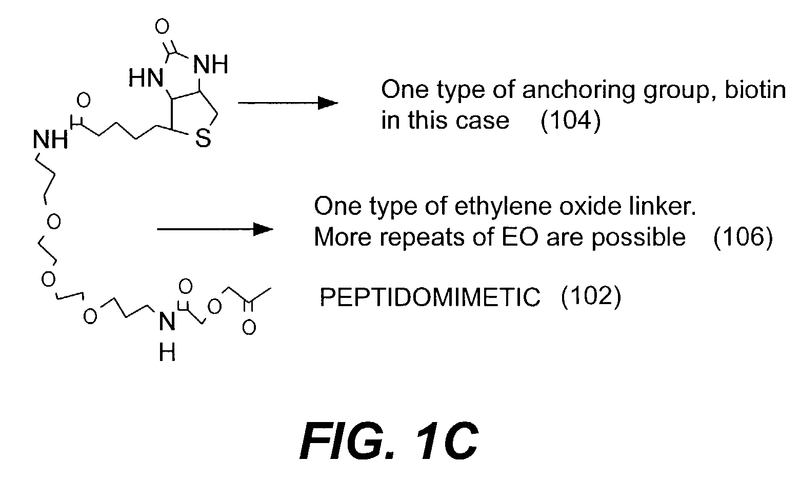
[0009]In one aspect, the invention pertains to an array of protein-binding agents stably attached to the mirrored surface of a solid support. The array includes a solid substrate having a substantially planar surface including an organic chemically-modified dielectric-coated reflective metal, and a plurality of different protein-binding agents bound to the substrate. Each of the protein-binding agents includes an anchoring segment stably bound to the substrate surface, a peptidomimetic protein-binding segment, and a linker segment connecting and separating the anchoring and peptidomimetic segments. The array may also include chemical blocking agents to prevent non-specific binding of proteins in samples run on the array.
[0010]In another aspect, the invention pertains to a method of making an array comprising a plurality of different protein-binding agents stably associated with the surface of a mirrored solid support. The method involves prepa

Problems solved by technology

This is likely due to the inherent instability of these materials at interfaces, and in the presence of complex biological matrices.
These techniques require the use of expensive custom-made masks that must be designed and manufactured for each chip.
Furthermore, chemical characterization of surface-synthesized peptides is nearly impossible to perform due to the tiny amount of peptide generated.
This method is problematic because the results are very sensitive to the experimental protocol (for example, development time of the gel as well as other parameters).
Therefore, it is very difficult to get reproducible data from 2-D gels.
Also, the sensitivity of the silver stain used in these gels is limited, and is less than that of the fluorescent labels used in microarray technologies.
In many cases, functional pathways cannot be directly linked to a particular gene.

Method used


Image

  • Microarrays on mirrored substrates for performing proteomic analyses
  • Microarrays on mirrored substrates for performing proteomic analyses
  • Microarrays on mirrored substrates for performing proteomic analyses

Examples


example 1

Preparation of Microtiter Plates Containing One Compound Per Well

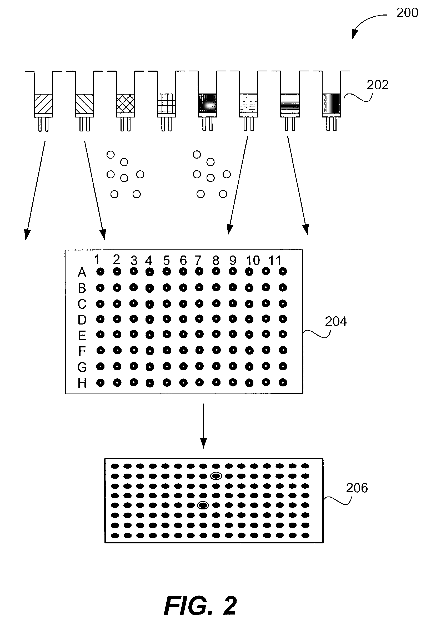
[0138]Preparation of one (1) 96-well plate containing 96 single compounds (0.8 mM) in a 1:1 DMSO / PBS solution: A siliconized vial (8 ml, 2 dram) was loaded with a one compound / bead library synthesized on Rink polystyrene macro-bead solid support (66 mg,˜1320 beads, 40 nanomole / bead, 0.75 mmol / g, 425–500 um, Polymer Laboratories) that contains a total of 121 possible compounds. The beads were swollen in dichloroethane (DCE, 4 ml) for 24 hours and sieved over stainless steel mesh (600 μm). Using the resulting dichloroethane bead slurry, 96 beads were individually picked and relocated into a polypropylene 96-well plate (200 μL, conical bottom) in order to obtain one bead per well over 96 wells. The resulting 96-well plate, (the ‘grandmother’ plate), was transferred to a speed-vac evaporator Savant AES200 equipped with a 96-well plate carrier rotor and the remaining DCE was removed from the plate. A cleavage cocktail (TFA / ...

example 2

Functionalization of Solid Supports for Spotting

[0141]Gold or aluminum reflective microscope slides were used as substrates for spotting a library of peptoids. In one example, the peptoid is functionalized with a thiol endgroup and the surface is functionalized with a maleimide. Upon spotting, the thiol on the peptoid reacts with the maleimide on the surface to form a covalent thioether attachment. Gold surfaces activated with maleimide were prepared as follows: 1) Gold-coated microscope slides (1200 Angstroms Au, 30–50 Angstroms Ti or Cr) were cleaned with Chromic acid cleaning solution for 15 minutes and rinsed with HPLC grade water. 2) Gold slides were dipped into 1–5 mM amino-modified thiol (1-Mercaptoundecyldiethoxyamine; a C-11 alkyl, two ethylene oxides, and an amine; alternatively, C-2 to C-20 alkyl groups and / or ethoxy or triethoxy groups could be used in such a compound) for 1–24 hours at room temperature or at 45 or 60° C. The slides were rinsed four times in absolute eth...

example 3

Derivatization of Aluminum / SiO2 Surfaces with Avidin

[0144]Aluminum slides coated with aminosilane were dipped into a solution of NHS-LC-LC-biotin (“LC” refers to 6-aminohexanoyl and “NHS” refers to N-hydroxysuccinimidyl) (commercially available from Pierce), depicted in FIG. 7A, that was 0.39 mM in PBS buffer. The slides were coated for 1.5 hours with shaking at 80 rpm. After attachment of biotin, the slides were rinsed with water, then dipped in a solution of 1 ug / ml–1 mg / ml avidin, streptavidin or neutravidin in PBS buffer for 2 hours, stirring at 70 rpm. The slides were rinsed with water and ready for spotting biotinylated peptides or peptoids. FIG. 7B depicts a representation of an avidin-derviatized aluminum slide spotted with a biotinylated protein-binding agent in accordance with one embodiment of the present invention.

[0145]The various surface modification steps was followed using ellipsometry to note the thickness changes. A thickness change increase of 40–45 angstroms was ...


PUM

PropertyMeasurementUnit
Thicknessaaaaaaaaaa
Dielectric polarization enthalpyaaaaaaaaaa

Abstract

Provided are peptidomimetic protein-binding arrays, their manufacture, use, and application. The protein-binding array elements of the invention include a peptidomimetic segment linked to a solid support via a stable anchor. The invention contemplates peptidomimetic array element library synthesis, distribution, and spotting of array elements onto solid planar substrates, labeling of complex protein mixtures, and the analysis of differential protein binding to the array. The invention also enables the enrichment or purification, and subsequent sequencing or structural analysis of proteins that are identified as differential by the array screen. Kits including proteomic microarrays in accordance with the present invention are also provided.

Description

CROSS-REFERENCE TO RELATED APPLICATIONS[0001]This application is a continuation-in-part of U.S. patent application Ser. No. 09 / 874,091 titled MICROARRAYS FOR PERFORMING PROTEOMIC ANALYSES, filed Jun. 4, 2001; which claims priority from U.S. Provisional Application No. 60 / 209,711, entitled MICROARRAYS FOR PERFORMING PROTEOMIC ANALYSES, filed Jun. 5, 2000; the disclosure of each of which is incorporated by reference herein in its entirety for all purposes.BACKGROUND OF THE INVENTION[0002]The present invention relates to cell product analysis and materials. In one embodiment, the invention is directed to proteomic microarrays and methods of using them to conduct proteomic analyses.[0003]In recent years, microarray technology has developed from a specialized subfield into an important tool for basic and applied studies in molecular biology, microbiology, pharmaceutics, agriculture, and many other biotechnologies. DNA microarray technology attempts to link the genome of an organism or ce...

Claims


Application Information

Patent Timeline
IPC IPC(8): C12M1/34C40B40/00C40B40/10C40B50/18G01N33/53C07K17/14C40B30/04G01N33/543G01N33/545G01N33/68G01N37/00
CPCB82Y15/00B82Y30/00B82Y40/00C07K17/14C40B30/04G01N33/543G01N33/545G01N33/6842G01N33/6845G01N2500/00
Inventor CHARYCH, DEBORAHBEAUSOLEIL, ERICZUCKERMANN, RONALD N.
Owner CHIRON CORP
Learn More