Titanium-aluminide turbine wheel and shaft assembly, and method for making same

a technology of titanium aluminum and turbine wheels, which is applied in the field of titanium aluminum turbine wheels and shaft assemblies, and the method of making same, and turbochargers, and can solve the problems of poor oxidation and creep resistance, poor high-temperature strength, and brittle alpha-2 phas

Active Publication Date: 2007-01-02
GARRETT TRANSPORATION I INC
View PDF12 Cites 37 Cited by
  • Summary
  • Abstract
  • Description
  • Claims
  • Application Information

AI Technical Summary

Benefits of technology

[0011]In a further embodiment of the invention, a titanium alloy member, such as a silver-titanium alloy member, is sandwiched between the wheel and a steel shaft and is brazed between the parts to join the parts together. The titanium alloy member preferably has a melting point of 650° C. to 750° C., i.e., low enough so that melting of the alloy member does not risk melting of the wheel or shaft, but high enough to prevent melting of the alloy member during service of the shaft-wheel assembly in a turbocharger. The alloy member can be brazed by electron beam.

Problems solved by technology

In terms of material properties, Ti3Al alpha-2 phase has good high-temperature strength but poor oxidation and creep resistance.
The alpha-2 phase is also extremely brittle and as such is difficult to weld effectively.
Even with the gamma phase, however, direct fusion-welding (e.g., by electron beam welding) of steel to titanium-aluminide is difficult to achieve without forming cracks in the weld zone.
Research in published literature has shown that solid-state cracking tends to occur in the weld zone as a result of high thermal stress and intrinsic brittleness of the welded microstructure.
In practice, however, it can be difficult to control these welding parameters as accurately as would be necessary to ensure crack-free welds.
Furthermore, even if crack-free welds are produced, there is still the possibility of post-weld cracking to occur when the welded component is introduced to an ambient atmosphere.
Welding of titanium-aluminide to a different material such as steel further increases the difficulty of producing satisfactory welds because of the potential for uncontrolled creation of various intermediate materials in the weld zone.
The resulting weld zone is brittle and requires a localized post-weld temper treatment to prevent fracture during machining of the finished component.
Simultaneously, progress has been offset by problems within the fusion zone, boundaries, and heat-affected zones of both parent materials because of to phase transformations and cracking phenomenon.

Method used


Image

  • Titanium-aluminide turbine wheel and shaft assembly, and method for making same
  • Titanium-aluminide turbine wheel and shaft assembly, and method for making same
  • Titanium-aluminide turbine wheel and shaft assembly, and method for making same

Examples


first embodiment

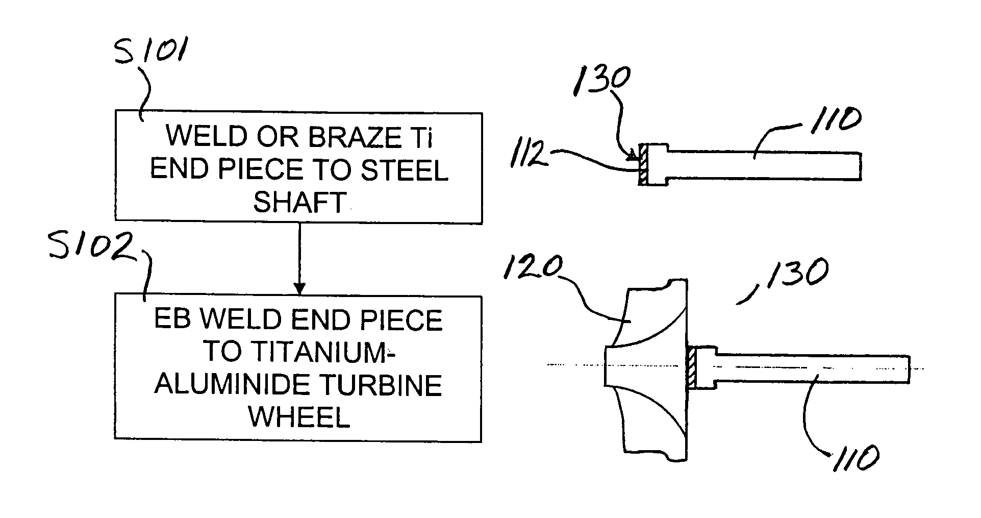
[0019]With reference to FIG. 1, the invention is illustrated. A steel shaft 110 is provided for joining with a titanium-aluminide turbine wheel 120. The shaft 110 can comprise a medium-carbon low alloy steel. The shaft has a joint surface 112 at its end for attachment to the turbine wheel. The turbine wheel can be formed of any of various titanium-aluminide intermetallic compounds.

[0020]In accordance with the first embodiment of the invention, an end piece 130 is provided as an intermediary between the steel shaft 110 and the titanium-aluminide turbine wheel 120. The end piece 130 is a titanium-containing member, and advantageously can comprise a substantially pure form of titanium or a titanium alloy. The end piece can be of various configurations such as in the form of a ring, a disk, or a slab. In a first step S101, the end-piece 130 is mechanically joined (brazed, bonded, or welded) to the shaft at the joint surface 112 and thus becomes a part of the shaft. The result of the fir...

second embodiment

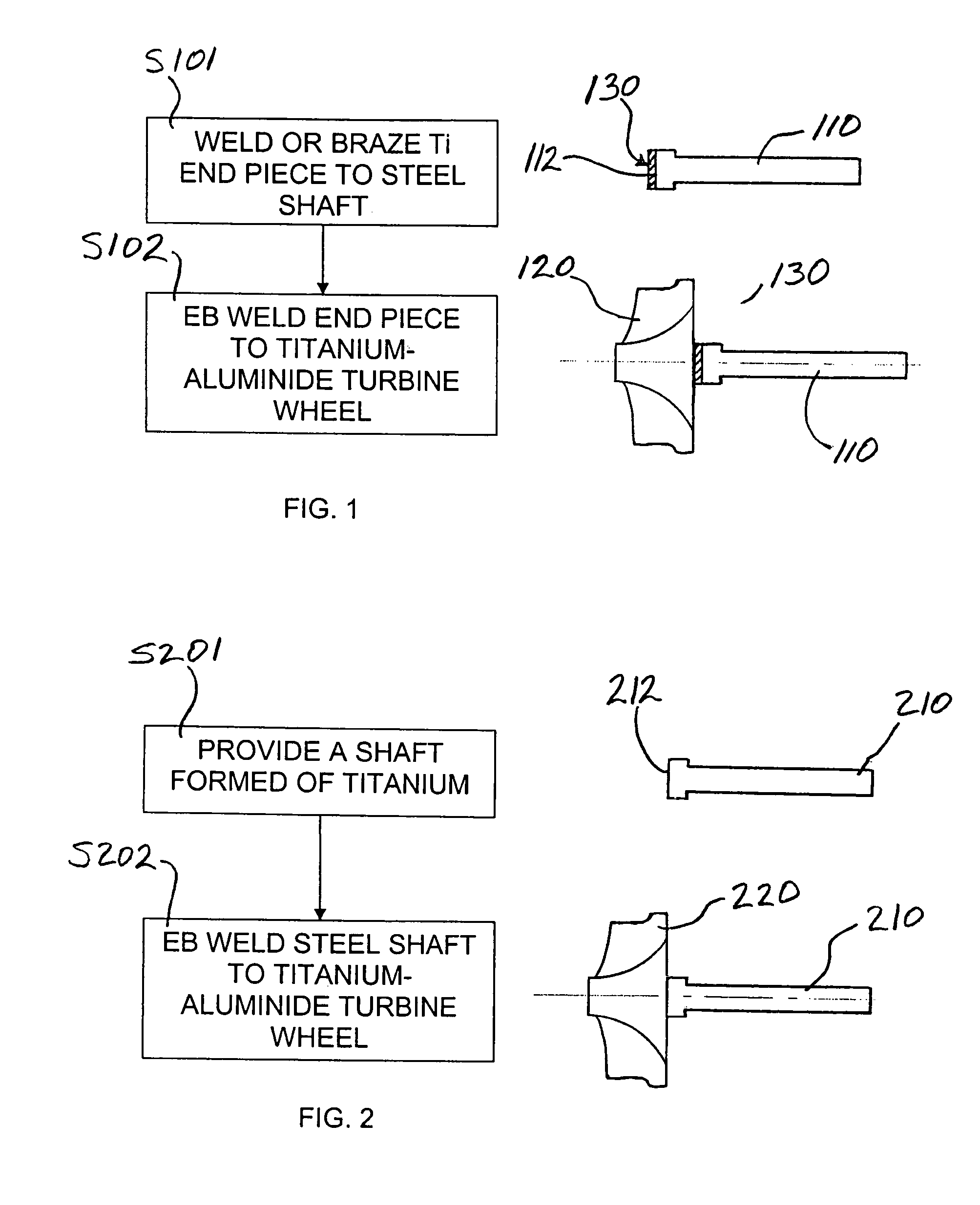
[0022]FIG. 2 illustrates the invention. A shaft 210 formed of titanium or titanium alloy is provided in a first step S201. For example, the shaft can be milled from titanium bar stock or titanium alloy bar stock. The shaft has a joint surface 212 for attachment to a turbine wheel. In a second step S202, a titanium-aluminide turbine wheel 220 is welded to the joint surface 212 of the shaft 210, such as by electron beam welding. The wheel is thus joined to the shaft to form a shaft assembly.

third embodiment

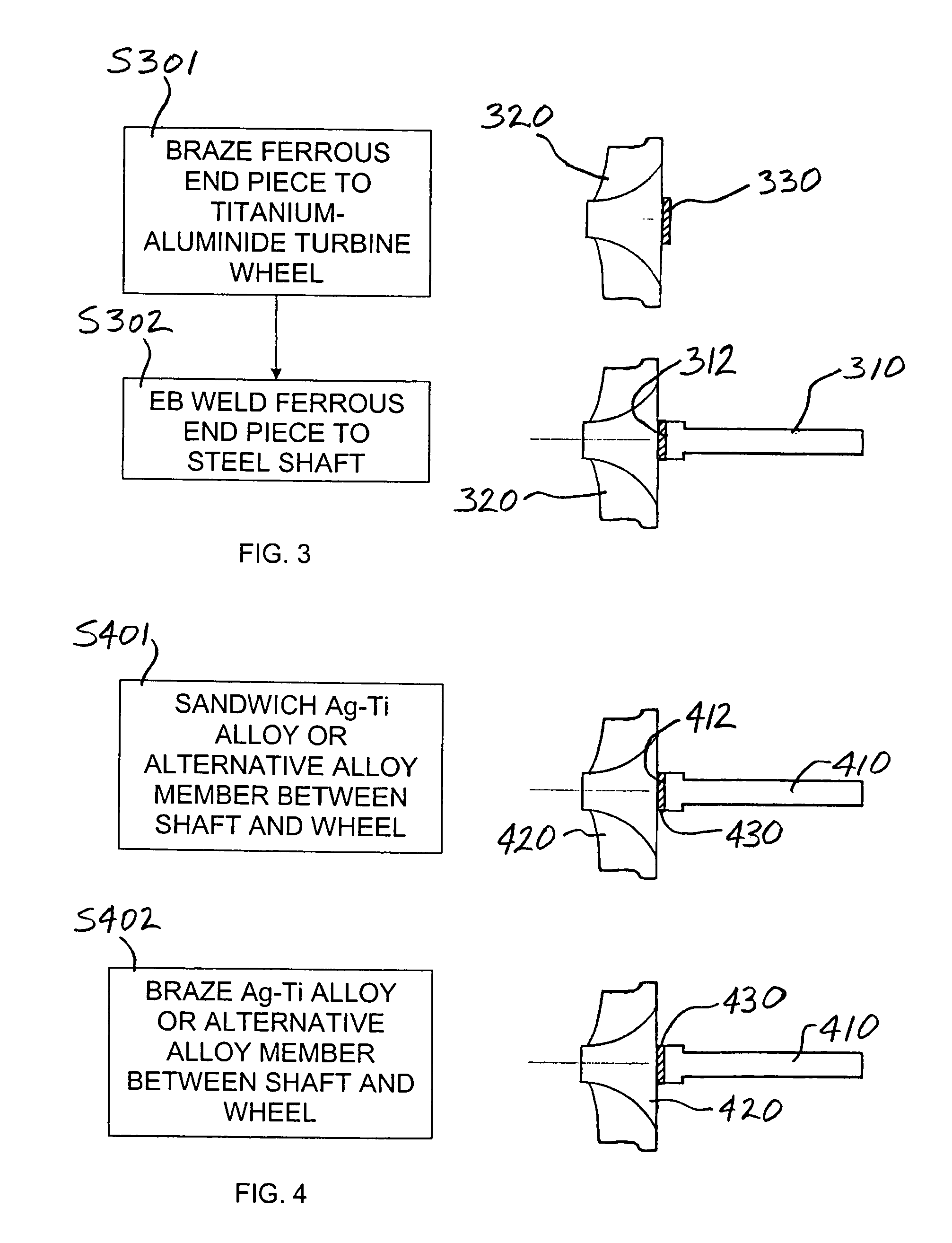
[0023]the invention is depicted in FIG. 3. In a first step S301, a ferrous end piece 330 is brazed to a titanium-aluminide turbine wheel 320. The end piece can comprise various ferrous-based materials, including but not limited to A286, HY-130, or HP9-4-20. In a second step S302, the ferrous end piece 330 is mechanically joined (brazed, bonded, or welded) at a joint surface 312 to a steel shaft 310. The shaft can be formed of various steel compositions. A suitable steel is a medium-carbon low alloy steel. The end piece 330 can be welded to the shaft 310 by electron beam welding. The wheel is thus joined to the shaft to form a shaft assembly.


PUM

PropertyMeasurementUnit
speedaaaaaaaaaa
melting pointaaaaaaaaaa
temperatureaaaaaaaaaa

Abstract

A titanium-aluminide turbine wheel (120, 220, 320, 420) is joined to the end of a shaft (110, 210, 310, 410) by utilizing a titanium surface on the end of the shaft to be joined to the wheel, and electron-beam welding the wheel onto the titanium surface on the shaft. A steel shaft (110, 310, 410) can have a titanium-containing end piece (130, 330, 430) mechanically joined (by brazing, bonding, or welding) to the end of the shaft, and the end piece can be directly electron-beam welded to the wheel. Alternatively, the shaft (210) can be formed as a titanium member and the end (212) of the shaft can be directly electron-beam welded to the wheel (220). In another embodiment, a ferrous end piece (330) is mechanically joined to the titanium-aluminide turbine wheel (320) and then the end piece is directly electron-beam welded to the end of a steel shaft (310). Alternatively, a silver-titanium alloy member (430) is sandwiched between the wheel (420) and a steel shaft (410) and is melted to join the parts together.

Description

BACKGROUND OF THE INVENTION[0001]The present invention relates to turbomachinery in general, and to turbochargers in particular. More specifically, the invention relates to a shaft assembly comprising a shaft joined to a titanium-aluminide turbine wheel, and to methods for making such a shaft assembly.[0002]Aluminides are intermetallic compounds. Aluminide-based alloys are attractive for various applications because they combine superior high-temperature performance with low specific gravity. In particular, titanium aluminide alloys are of current interest for manufacturing turbine wheels for turbomachinery such as turbochargers. The gamma-phase titanium-aluminide alloys appear to be especially useful.[0003]There are two basic forms of titanium-aluminide: Ti3Al alpha-2 phase containing between 22% and 39% aluminum, and TiAl gamma phase containing between 49% and 66% aluminum. There is also an orthorhombic form containing between 12.5% and 30% niobium, generally denoted as Ti2AlNb (O...

Claims


Application Information

Patent Timeline
Patent Type & Authority Patents(United States)
IPC IPC(8): B23K31/02
CPCB23K1/0018B23K15/0093B23K15/04B23K31/02F01D5/025B23K15/008Y10T428/12806B23K2201/001B23K2203/04B23K2203/14B23K2203/18B23K2203/24F05D2220/40F05D2230/233F05D2230/237B23K2101/001B23K2103/04B23K2103/05B23K2103/14B23K2103/18B23K2103/20B23K2103/24
Inventor RENAUD, PHILLIPEWILSON, MARC
Owner GARRETT TRANSPORATION I INC
Why Eureka
Try Eureka