Porous polymer water filter and methods of use in refrigeration

a polymer water filter and polymer technology, applied in the field of porous polymer water filters and methods of use in refrigeration, can solve the problems of affecting the performance of loose bed activated carbon filters in specific areas, occupying too much space for many point-of-use applications, and limited use of carbon blocks, etc., to achieve a large surface area, increase the bonding capability and density of the filter, and increase the average particle size

Inactive Publication Date: 2007-01-30
3M INNOVATIVE PROPERTIES CO
View PDF118 Cites 50 Cited by
  • Summary
  • Abstract
  • Description
  • Claims
  • Application Information

AI Technical Summary

Benefits of technology

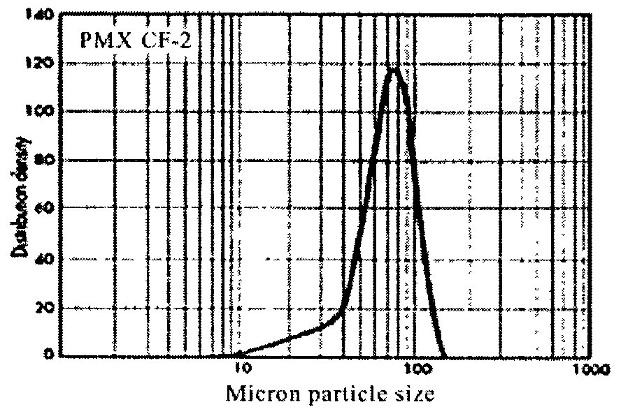
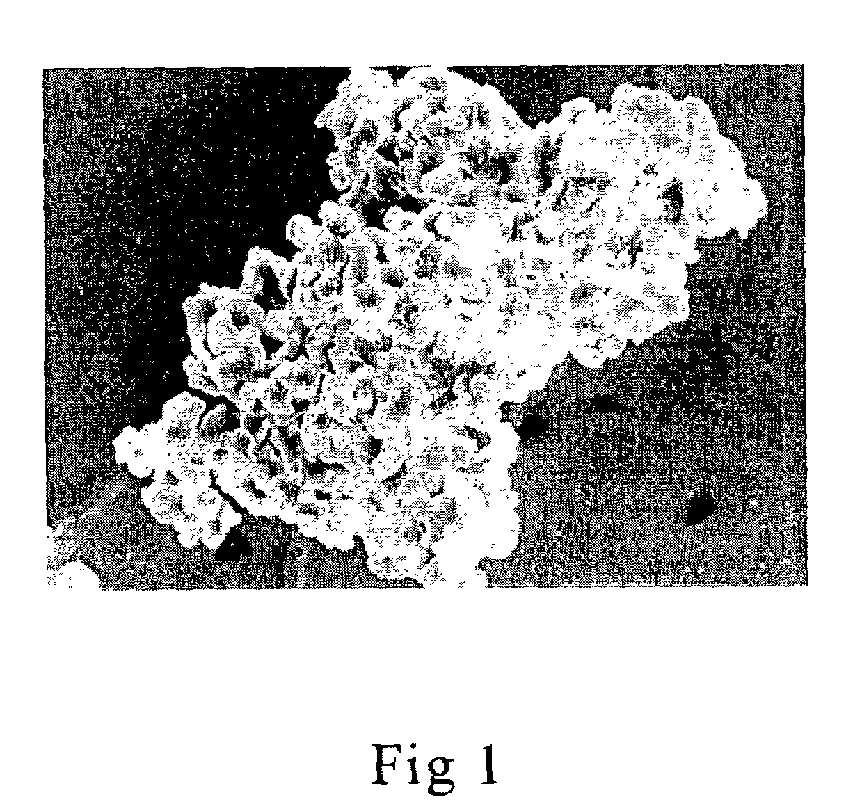
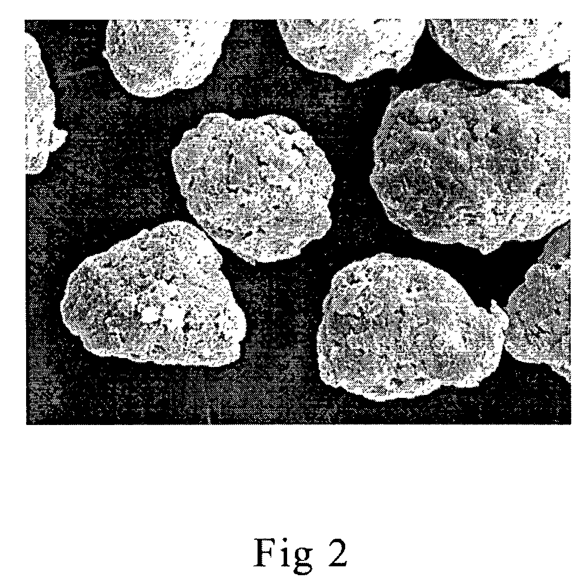
[0011]The method of processing involves the vigorous vibration of powdered filtering materials and polymer until they are firmly compacted into a given space such as a mold cavity. Pockets of air creating unnecessary voids between the particles are reduced in this manner. This achieves the maximum amount of density of materials without external force. The absence of force allows both the polymeric material and the filtering compounds to retain their original shape (morphology) and particle size. The two polymers of the preferred embodiment have distinctly different morphologies with each providing different characteristics to the resulting filter.
[0012]Thus the morphology of the two principal polymeric materials allows the filter matrix to be manipulated by adjusting the ratio between the two polymers, accentuating one attribute over another. The mean parti

Problems solved by technology

The origin came from the need to improve upon the use of loose bed carbon particles that have been utilized to remove organic contaminants from water since Roman times. However, loose bed activated carbon filters lack performance in specific areas and, as a practical matter, take up too much space for many point-o

Method used


Image

  • Porous polymer water filter and methods of use in refrigeration
  • Porous polymer water filter and methods of use in refrigeration
  • Porous polymer water filter and methods of use in refrigeration

Examples


Embodiment Construction

[0024]The filtration device of the present invention relies on (i) a unique method of processing to achieve maximum density of materials with uniform particle distribution, (ii) a combination of polymeric materials having distinctly different morphologies to create a formed, structural filtration matrix and (iii) a polymeric material having a very small micron diameter that enhances the use of finely powdered filtering compounds. These compounds may include adsorbents, such as but not limited to granular and powdered activated carbon, metal ion exchange zeolite sorbents such as Engelhard's ATS, activated aluminas such as Selecto Scientific's Alusil, ion exchange resins, silver, zinc and halogen based antimicrobial compounds, acid gas adsorbents, arsenic reduction materials, iodinated resins, textile fibers, as well as other polyethylene polymers. The formation of a structural filtration matrix accommodates the presence of filtering compounds, which may be formulated to a specific ta...


PUM

PropertyMeasurementUnit
Lengthaaaaaaaaaa
Lengthaaaaaaaaaa
Lengthaaaaaaaaaa

Abstract

The filtration device of the present invention relies on materials and methodologies that achieve the formation of a structural matrix that may later accommodate the addition of other adsorbent materials as opposed to merely binding adsorbent materials together through the use of compression and/or binder materials. The filter device of the present invention relies on (i) a unique method of processing to achieve maximum density of materials, (ii) a polymeric material having a distinct morphology and (iii) a very small micron diameter of the polymeric material to create uniformity. For example, in place of compression to increase density, the materials comprising the filtration device of the present invention are instead vibrated into a mold cavity. Thus, the methodology of the current invention optimizes how all of the materials comprising the filtration device fit together without compaction. The material being processed is vibrated as it is gradually poured into the mold. Once the mold cavity has been filled to a point where it will hold no more material, it is heated and then cooled. In place of an external binder, the structural material adheres to itself as it softens. This results in a tortuous path matrix of pores rather than an absolute pore barrier.

Description

BACKGROUND OF THE INVENTION[0001]1. Field of the Invention[0002]The present invention relates to filtration devices, novel methods for the production of the same and methods of use. More specifically, the present invention relates to a methodology of vibrating and then sintering polymers having distinct morphologies to achieve a structural filtration matrix, which is also capable of accommodating various compounds for the removal, reduction or adsorption of undesirable contaminants in liquids and gases, most notably water and air.[0003]2. Description of the State of Art[0004]The filtration of fluids may be accomplished through a variety of technologies, the selection of which is often determined by the contaminant or contaminants that are being targeted for removal or reduction. Particulates are best removed through a process known as depth filtration. The filter collects and holds any dirt or sediment within its matrix. Dissolved organic contaminants appearing on a molecular level ...

Claims


Application Information

Patent Timeline
IPC IPC(8): B01D39/00B01D24/00
CPCB01D39/1653B01D39/2062Y10T428/254B01D2239/0442B01D2239/1241B01D2239/0407
Inventor HUGHES, DOUGLASS E.BUHLER, RICH
Owner 3M INNOVATIVE PROPERTIES CO
Why Eureka
Try Eureka