Active filter for reduction of common mode current

Inactive Publication Date: 2007-03-06
INFINEON TECH AMERICAS CORP
View PDF6 Cites 27 Cited by
  • Summary
  • Abstract
  • Description
  • Claims
  • Application Information

AI Technical Summary

Benefits of technology

[0031]A novel architecture is also provided, enabling the use of a very small toroidal current transformer as the common mode sensor. Unlike the architecture in FIG. 1, which requires a high gain, this novel architecture requires a gain of only unity, and

Problems solved by technology

High-speed switching, however, causes the following serious problems, originating from a high rate-of-change in voltage and/or current:a) ground current escaping to earth through stray capacitors inside motors and through long cables;b) conducted and radiated EMI;c) motor bearing current and shaft voltage; andd) shortening of insulation life of motors and transformers.
The voltage and/or current change caused by high-speed switching produces high-frequency oscillatory common-mode and normal-mode currents when the switching device(s) change state because parasitic stray capacitance inevitably exists inside a load, for example, an ac motor, as well as inside the switching converter.
The common mode oscillatory currents may have a frequency spectrum range from the switching frequency of the converter to several tens of MHZ, which creates a magnetic field and will produce radiated electromagnetic interference (EMI) throughout, thus adversely affecting electronic devices such as radio receivers, medical equipment, etc.
Generally, common-mode chokes and EMI filters, based on passive elements, may not completely solve these problems.
Passive common mode filters may place limits on the PWM frequency which can be used, are physically large (frequently a major fraction of the volume of the motor drive structure) and are expensive.
Further, they are

Method used


Image

  • Active filter for reduction of common mode current
  • Active filter for reduction of common mode current
  • Active filter for reduction of common mode current

Examples


Embodiment Construction

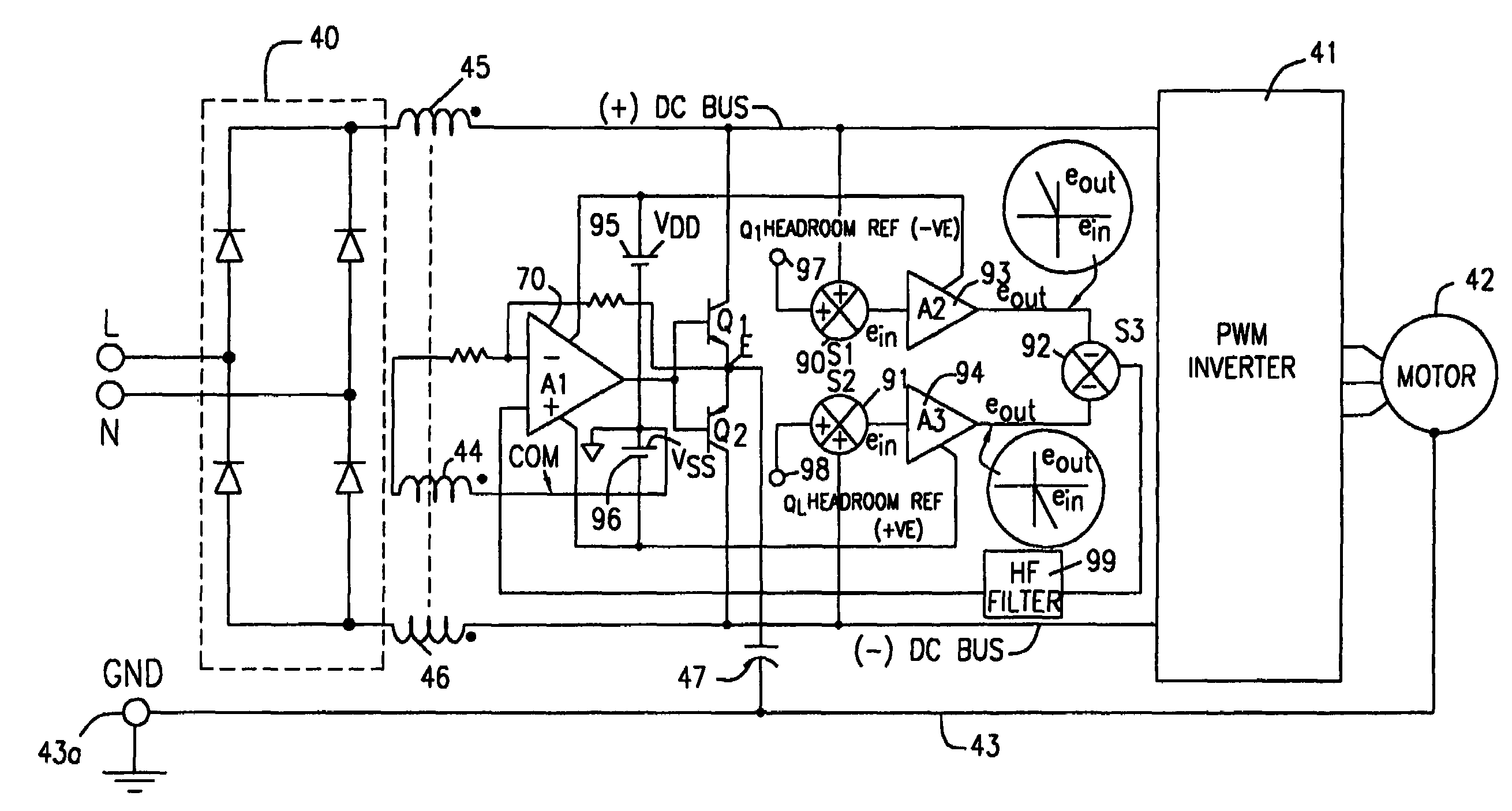
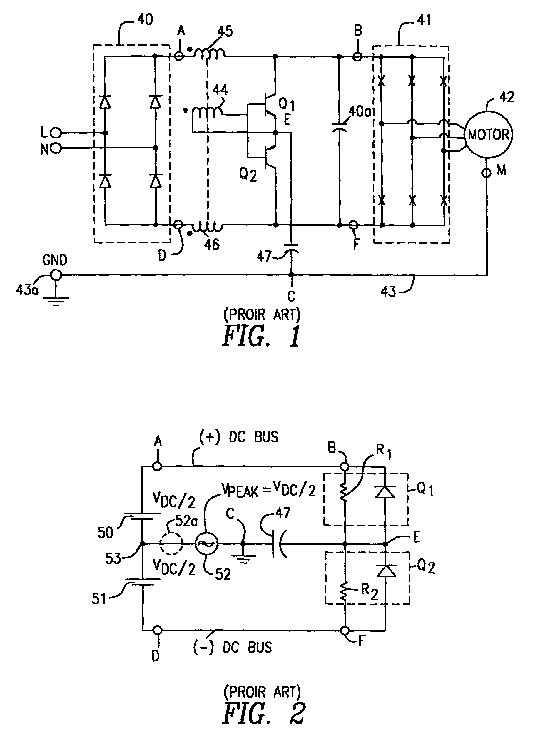
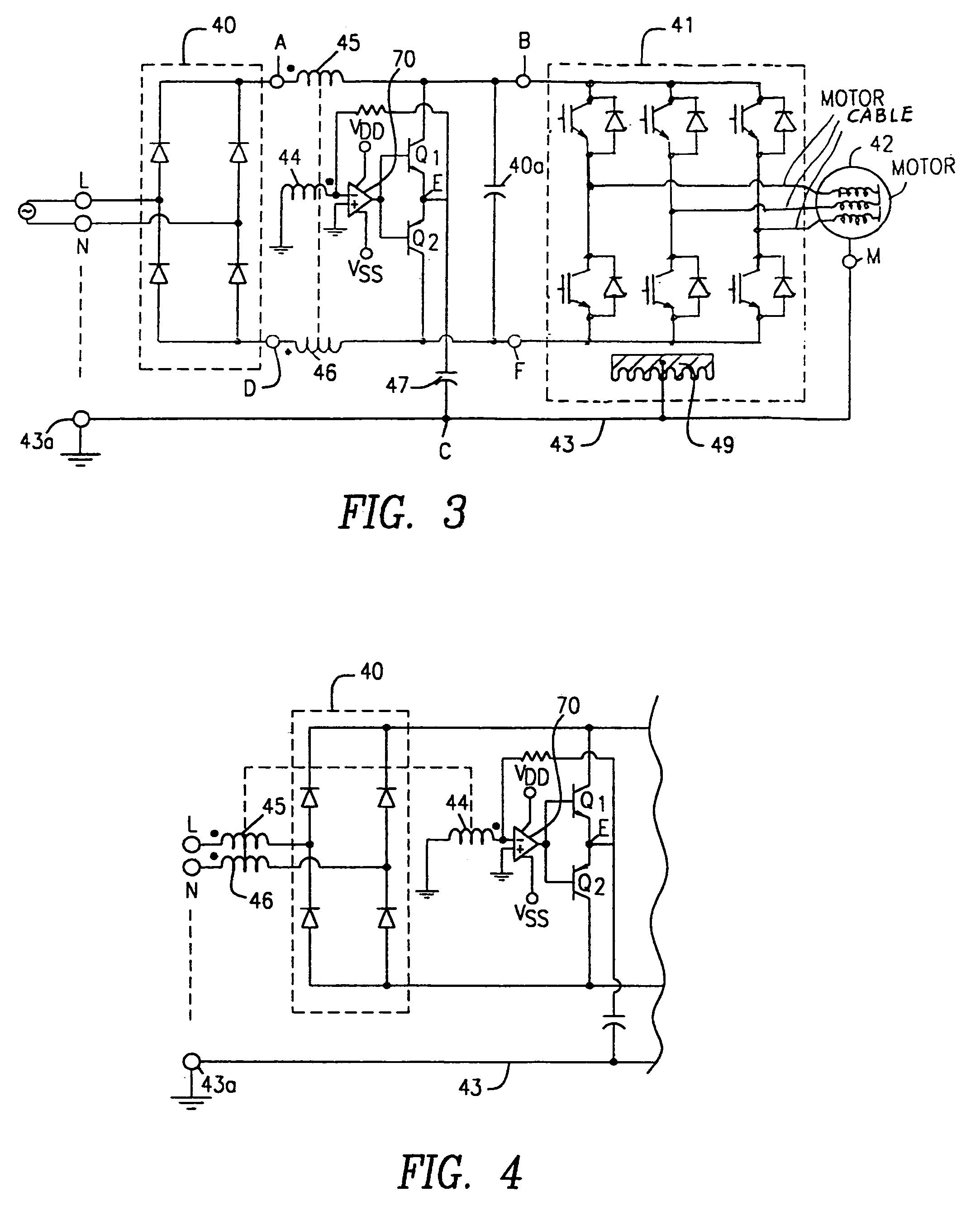
[0058]FIG. 3 shows an improvement of the circuit of FIG. 1 wherein like numerals designate similar components as is true throughout this specification. FIG. 3 further shows, in schematic fashion, a heat sink 49 which receives the IGBTs (or MOSFETs) of the PWM inverter 41. Heat sink 49, like the housing of motor 42, is connected to ground line 43. In FIG. 3, however, a novel improvement is added which permits a substantial reduction in the size of the transformer 44, 45, 46 without affecting the operation of the active filter function. Thus, in FIG. 3, an operational amplifier 70 is added to the circuit to act as a buffer / amplifier between the secondary of the common mode current sensing transformer 44, 45, 46 and the transistors Q1 and Q2. This permits the size and cost of transformers 44, 45, 46 to be substantially reduced.

[0059]While the primary windings 45 and 46 of the common mode transformer are shown in FIG. 3 at the output of rectifier 40, they may be placed in the a-c input ...


PUM


Abstract

An active filter for reducing the common mode current in a pulse width modulated drive circuit driving a load, said drive circuit comprising an a-c source, a rectifier connected to said a-c source and producing a rectified output voltage connected to a positive d-c bus and a negative d-c bus, a PWM inverter having input terminals coupled to said positive d-c bus and negative d-c bus and having a controlled a-c output, a load driven by said a-c output of said PWM inverter, a ground wire extending from said load, and a current sensor for measuring the common mode current in said drive circuit in said ground wire, said current sensor producing an output current related to said common mode current, said active filter comprising a first and second MOSFET transistor, each having first and second main electrodes and a control electrode, and an amplifier driving a respective one of the transistors; said first electrode of said first and second transistor coupled to a common node, said second electrodes of said first and second transistors being coupled to said positive d-c bus and said negative d-c respectively; each of said amplifiers having an input coupled to said output of said current sensor and each having an output connected to a respective one of said control electrodes; and a d-c isolating capacitor connecting said common node of said first electrode of said first and second transistors to said ground wire.

Description

CROSS REFERENCE TO RELATED APPLICATIONS[0001]This application is a continuation of U.S. patent application Ser. No. 10 / 609,273, filed Jun. 26, 2003 now U.S. Pat. No. 6,794,929 entitled “ACTIVE FILTER FOR REDUCTION OF COMMON MODE CURRENT” which application is a divisional of U.S. patent application Ser. No. 09 / 816,590, filed Mar. 23, 2001, now U.S. Pat. No. 6,636,107, in the name of Brian R. Pelly and entitled ACTIVE FILTER FOR REDUCTION OF COMMON MODE CURRENT” which application is related to and claims priority to Provisional Application Ser. Nos. 60 / 192,976, filed Mar. 28, 2000 and 60 / 211,999 filed Jun. 16, 2000.FIELD OF THE INVENTION[0002]This invention relates to filters for electrical circuits and more specifically relates to an active filter for reducing or redirecting the common mode current in switch mode power supplies and particularly for reducing the common mode current and EMI in a PWM motor drive circuit.BACKGROUND OF THE INVENTION[0003]High-speed switching devices such ...

Claims


Application Information

Patent Timeline
IPC IPC(8): H03K5/00H02M1/12H02M5/458
CPCH02M1/12H02M5/458H02P29/0038H02P2201/07H02M2001/123H02P29/50H02M1/123
Inventor PELLY, BRIAN R.
Owner INFINEON TECH AMERICAS CORP
Why Eureka
Try Eureka