Method and apparatus for fiberscope

a fiber optic probe and fiber optic tube technology, applied in the direction of optical radiation measurement, diagnostics using spectroscopy, instruments, etc., can solve the problems of limited application of chemical imaging outside the research laboratory, blood and bodily fluids limiting the viewing, identification and ability to perform in vivo optical measurements of suspect areas, and the limitations of the raman fiber optic probe devi

Active Publication Date: 2007-05-15
CHEMIMAGE CORP
View PDF29 Cites 35 Cited by
  • Summary
  • Abstract
  • Description
  • Claims
  • Application Information

AI Technical Summary

Benefits of technology

[0016]In still another embodiment, the disclosure relates to a method of imaging and collecting optical spectra from a sample, the method comprising the steps of providing a fiberscope including at least one illumination fiber operatively connected at a proximal end to a first light source and a second light source so as to transmit light from said first and second light sources to a dichroic mirror disposed in proximity to a distal end of the fiberscope; at least one collection fiber for receiving light from said illuminated sample and transmitting the received light to an optical device; and a dichroic mirror disposed at the distal end of the fiberscope which allows light from the first light source to pass substantially straight through the mirror while substantially reflecting light from the second light source toward the sample to thereby illuminate the sample.

Problems solved by technology

The application of chemical imaging outside the research laboratory has been limited by the lack of availability of stable imaging platforms that are compatible with the physical demands of industrial process monitoring and clinical environments.
In addition, for in vivo cardio-vascular clinical applications, the presence of blood and bodily fluids limits the viewing, identification and ability to perform in vivo optical measurements of suspect areas.
Previously described Raman fiber optic probe devices have several limitations.
First, current fiber-optic-based Raman probes are sensitive to environmental variability.
These devices often fail to function properly when the probe is subjected to hot, humid and / or corrosive environments.
Normally, incorporation of a window into a probe would introduce a significant engineering problem.
The back reflected light corrupts the quality of the analysis.
Previous probe designs are also inadequate because of the environmental sensitivity of the spectral filters that are employed in the devices.
Past spectral filters have traditionally been fabricated using conventional thin film dielectric filter technology which are susceptible to temperature and humidity induced degradation in the filter spectral performance.
Another limitation of current probe technologies is that none combine the three basic functions of the chemical imaging fiberscope: (1) video inspection; (2) spectral analysis; and (3) chemical image analysis in an integrated, compact device.
AOTFs suffer from image artifacts and instability when subjected to temperature changes.
One problem in performing chemical analysis and chemical imaging in the human body, such as in for example, in the cardio-vascular system or body cavities during, for example, endoscopic surgery, is the occurrence of significant amounts of blood and water at the sample site which both scatters and absorb light in certain wavelength ranges.
However, such NIR wavelengths are poorly suited for performing Raman scattering or fluorescence measurements.
Other current methods for characterizing vulnerable plaque such as Intra Vascular UltraSound (IVUS) and thermometry (e.g., Volcano Therapuetics, Inc.) map out some physical properties of the arterial walls to suggest likely areas of plaques, but are not chemically specific and cannot provide any detailed analytical information regarding the chemical state or molecular composition of these target areas or plaques.
Optical imaging to position a chemical probe in vivo is desirable but problematic and limited due to the scattering and absorption properties of blood.
While certain optical wavelengths in the NIR are known to be more favorable than others for in vivo viewing of the cardiovascular system, these wavelengths are not well-suitable for performing highly specific chemical analysis.
The low cost, high sensitivity Si charge-coupled detectors (“CCD”) used for Raman Chemical imaging also have reduced sensitivity for longer wavelength Raman scattered peaks thereby making it difficult to detect the very important CH-bond vibrational region.

Method used


Image

  • Method and apparatus for fiberscope
  • Method and apparatus for fiberscope
  • Method and apparatus for fiberscope

Examples


Embodiment Construction

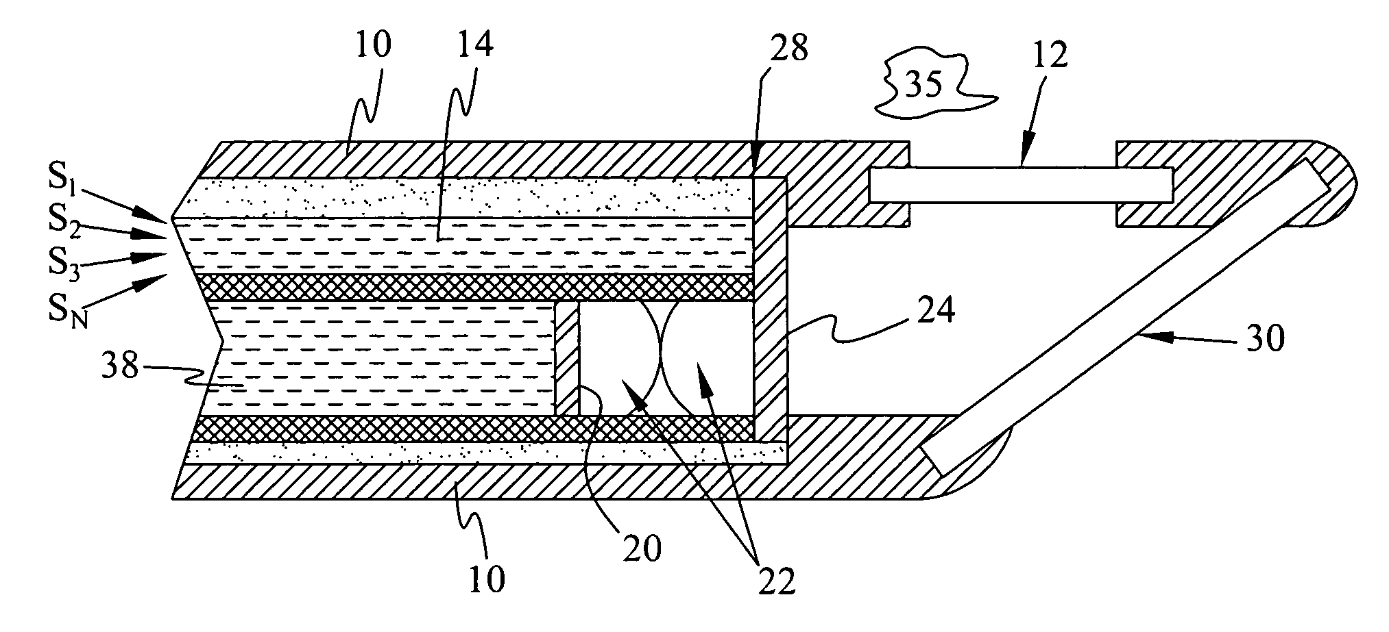
[0035]The Raman chemical imaging fiberscope combines in a single platform a laser beam delivery system to irradiate samples for Raman spectroscopy, an incoherent fiber optic bundle to deliver white light illumination and a coherent fiber bundle suitable for Raman spectral collection, Raman image collection and digital video collection.

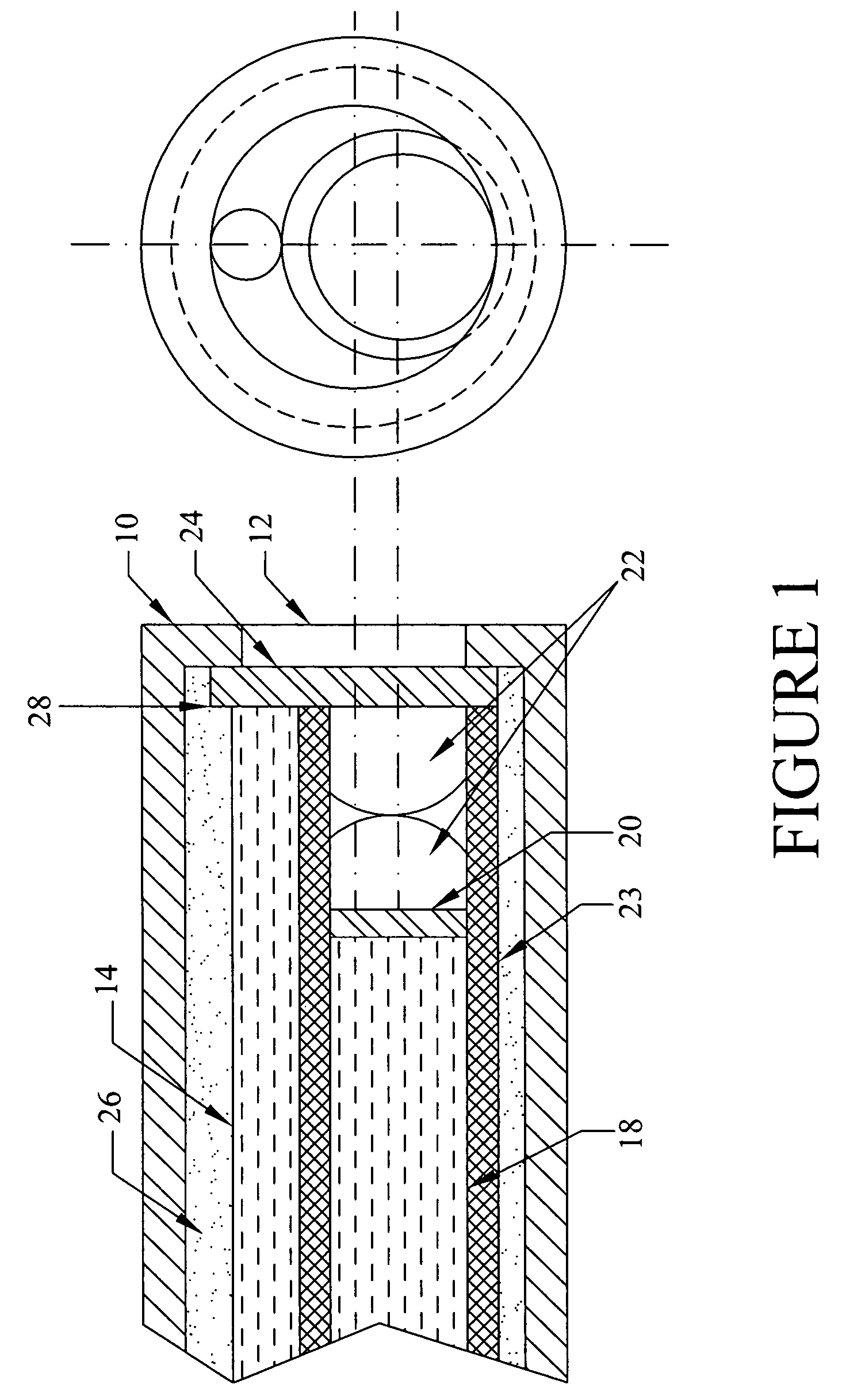
[0036]The distal end of the fiberscope is shown in cross-section in FIG. 1. The external housing 10 surrounds the inner core of the fiberscope. The outer jacket 10 is mechanically rugged and immune to hostile sampling environments. The compression tube 23 holds the fibers 18, the filter 24 and lens 22 in alignment. At the distal end of the fiberscope is window 12. This window is, in one embodiment, composed of quartz, diamond or sapphire and is used as an optically transparent boundary separating the sample environment from the optical components in the probe. In an alternative embodiment, the other biocompatible material such as plastics, glass or sem...


PUM


Abstract

The disclosure generally relates to a method and apparatus for a fiberscope. In one embodiment, the disclosure relates to a chemical imaging fiberscope for imaging and collecting optical spectra from a sample having at least one illumination fiber for transmitting light from a first an a second light source to a distal end of a fiberscope; a dichroic mirror disposed at said distal end of the fiberscope such that light from said first light source passes substantially straight through said mirror and light of a predetermined wavelength from said second light source is substantially reflected by said mirror toward said sample to thereby illuminate said sample; and at least one collection fiber for receiving light from said illuminated sample and transmitting the received light to an optical device.

Description

[0001]The instant application claims the filing-date benefit of application Ser. Nos. 10 / 934,885 and 10 / 935,423, filed Sep. 3, 2004 and Sep. 7, 2004, respectively. Each of said applications claims the filing date benefit of application Ser. No. 09 / 619,371 (now U.S. Pat. No. 6,788,860) filed Jul. 19, 2000, which itself claims the filing-date benefit of Provisional Application No. 60 / 144,518 filed Jul. 19, 1999. Reference is also made to application Ser. Nos. 09 / 976,391 (now U.S. Pat. No. 6,734,962) and Ser. No. 09 / 064,347 (now U.S. Pat. No. 6,002,476) which are assigned to the assignee of the instant application. The specifications of each of the above-identified applications is incorporated herein in its entirety for background information.BACKGROUND[0002]Chemical imaging combines optical spectroscopy and digital imaging for the molecular-specific analysis of materials. Raman, visible, near infrared (VIS / NIR) and Fluorescence chemical imaging have traditionally been performed in lab...

Claims


Application Information

Patent Timeline
Patent Type & Authority Patents(United States)
IPC IPC(8): G02B6/06A61B1/06G01J3/44
CPCA61B1/00165A61B1/07A61B5/0075A61B5/0084G01J3/02G01J3/021G01J3/0218G01J3/0256G01J3/0264G01J3/0291G01J3/32G01J3/44G01N21/474G01N21/645G01N21/65G02B23/2423G02B23/2469A61B1/043G01J2003/1213G01N21/33G01N21/359G01N2021/3155G01N2021/4742G01N2021/6419G01N2021/6421G01N2021/6484G01N2021/656G02B6/06G02B6/29398
Inventor TREADO, PATRICK J.NELSON, MATTHEWDEMUTH, JOSEPH E.
Owner CHEMIMAGE CORP
Why Eureka
Try Eureka