High-frequency magnetic thin film, composite magnetic thin film, and magnetic device using same

a technology of composite magnetic and thin film, which is applied in the direction of magnetic bodies, inductances, and substrates/intermediate layers, can solve the problems of lowering reducing the manufacturing cost of mmic, and consuming a large amount of expensive semiconductor substrates. , to achieve the effect of preventing the growth of fe—c grains, excellent soft magnetic properties, and suppressing the degradation of soft magnetic properties

Inactive Publication Date: 2007-05-29
TDK CORPARATION
View PDF13 Cites 13 Cited by
  • Summary
  • Abstract
  • Description
  • Claims
  • Application Information

AI Technical Summary

Benefits of technology

[0015]As the above mentioned, the resonance frequency can be increased by increasing the anisotropy magnetic field and the saturation magnetization of the material and thereby the usable limit frequency can be increased. Now, a calculation is made on the basis of the above formula (1) on the anisotropy magnetic field required for increasing up to 2 GHz the resonance frequency of the CoZrNb amorphous alloy thin film, which is a typical example of conventional Co-based amorphous alloy thin films. Consequently, the calculation reveals that the anisotropy magnetic field of 44 Oe (3501.52 A / m) or more is required. As can be seen from this calculated result, the film concerned which usually has an anisotropy magnetic field of the order of 15 Oe (1193.7 A / m) is hardly applicable to the GHz frequency region. On the other hand, the anisotropy magnetic field required for actualizing the resonance frequency of 2 GHz is 36 Oe (2864.88 A / m) for the saturation magnetization of 14 kG (1.4 T) and 28 Oe (2228.24 A / m) for the saturation magnetization of 18 kG (1.8 T); thus it can be expected that incorporation of an Fe-based alloy or an FeCo-based alloy, both high in saturation magnetization and magnetic crystalline anisotropy, realizes the required saturation magnetization and anisotropy magnetic field.
[0018](1) An Fe—C thin film having a predetermined thickness has columnar structure, but when the thickness is of the order of 70 nm or less, excellent soft magnetic properties can be obtained because the aspect ratio of the columnar structure (the ratio of the column length to the column width, the length / the width) is small. More specifically, the average width of the grown Fe—C columns is about 50 nm, and the degradation of the soft magnetic properties due to the columnar structure can be suppressed as far as the thickness is of the order of 70 nm for which the aspect ratio of the columnar structure is 1.4 or less. For the purpose of obtaining an Fe—C thin film having such an aspect ratio, as shown in FIG. 3, it is effective that a Co-based amorphous alloy thin film 111 is interposed between an Fe—C thin film 112 and another Fe—C thin film 112. In this way, the continuous columnar growth of the Fe—C grains can be prevented.
[0019](2) Elaborate examination of the growth process of the Fe—C thin film has revealed that a microcrystalline state of 3 nm or less in grain size is found in the early stage of the film growth with the film thickness of the order of 3 nm or less, and the unstable surface ratio is increased, so that the features of an amorphous substance are exhibited. More specifically, as shown in FIG. 4, the Fe—C thin film 121 is constituted with an amorphous structure portion 121a formed on the substrate 120 and a columnar structure portion 121b formed on the amorphous structure portion 121a. Being amorphous can be judged for the case of the Fe—C thin film, on the basis of the X-ray diffraction, from the absence of the diffraction peak ascribable to the Fe—C bcc (110) crystal plane. A thin film having such amorphous structure, needless to say, does not turn into columnar structure, and can yield high resistance (100 μΩ cm or more) properties attributable to amorphous structure. Accordingly, adoption of a form in which the film concerned is laminated with a Co-based amorphous alloy thin film can actualize the soft magnetic properties, needless to say, and high resistance, so that a magnetic thin film high in permeability in the GHz frequency region, suppressed in eddy current loss and high in quality factor can be obtained.
[0021]In other words, as described above, the present invention has made it possible to provide a high frequency composite magnetic thin film which can easily attain the properties, in the GHz region (1 GHz), such as the real part (μ′) of the permeability of 200 or more, the quality factor Q (Q=μ′ / μ″) of 1 or more and the saturation magnetization of 12 kG (1.2 T) or more, by laminating a Co-based amorphous alloy thin film excellent in soft magnetic properties and an Fe—(C, B, N) thin filmoran FeCo—(C, N, B) thin film, both having high saturation magnetization and high magnetic anisotropy field.

Problems solved by technology

The occupation of larger areas by the passive elements as a result leads to mass consumption of expensive semiconductor substrates, namely, the cost rise of the MMIC.
Accordingly, now it is a challenge to reduce the areas occupied by the passive elements for the purpose of reducing the chip area and thereby lowering the manufacturing cost of the MMIC.
However, when a magnetic thin film made of an Fe-based alloy or an FeCo-based alloy is prepared by means of a deposition technique such as the sputtering technique, the saturation magnetization of the film obtained is high, but the coercivity thereof is high and the resistivity thereof is low, so that satisfactory high frequency properties thereof can be hardly obtained.
However, this method involves a problem such that the production process tends to be complicated and additionally the effective permeability of the magnetic thin film is lowered.
However, the multilayer film methods involve the insertion of the high electric resistance nonmagnetic phase and hence lead to a problem such that the saturation magnetization is lowered.
In the case of the metal-nonmetal granular film, a permeability is 200 or less, leading to a problem that the permeability is low.
However, any one of these combinations cannot yield high permeability in the high frequency region, no application to the GHz frequency region being able to be expected.

Method used


Image

  • High-frequency magnetic thin film, composite magnetic thin film, and magnetic device using same
  • High-frequency magnetic thin film, composite magnetic thin film, and magnetic device using same
  • High-frequency magnetic thin film, composite magnetic thin film, and magnetic device using same

Examples


example 1

[0096]According to the following deposition technique, a high frequency magnetic thin film of the present invention was prepared.

[0097]An Si wafer on which a 100 nm thick SiO2 was deposited was used as the substrate.

[0098]The high frequency magnetic thin film was deposited on the substrate by use of a faced-targets sputtering apparatus and according to the following techniques. Preliminary evacuation of the interior of the faced-targets sputtering apparatus was carried out to 8×10⁻⁵ Pa, thereafter Ar gas was introduced into the apparatus until the pressure reached 10 Pa, and then the substrate surface was subjected to sputter etching at an RF power of 100 W for 10 minutes.

[0099]Subsequently, the Ar gas flow rate was adjusted so as for the pressure to be 0.4 Pa, at a power of 300 W, a Co87Zr5Nb8 target and a composite target composed of an Fe target and C (carbon) pellets arranged thereon were alternately and repeatedly subjected to sputtering, and thus a composite magnetic thin film...

example 2

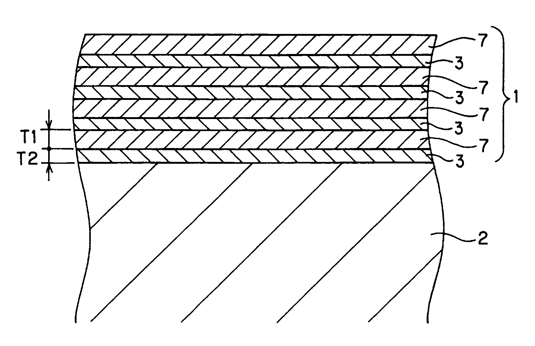
[0105]On the basis of the above described deposition technique of Example 1, a 20 nm thick CoZrNb layer and a 20 nm Fe—C layer (carbon concentration: 5 at %) were alternately laminated each in 13 layers in a successive manner, and thus a composite magnetic thin film (Example 2) of the present invention having a total film thickness of 520 nm (26 layers in total) was formed.

[0106]Examination of the structure of the composite magnetic thin film confirmed that the Fe—C layers were mainly constituted with columnar grains and the aspect ratio of the columnar structure portion was 1.4 or less. Additionally, the CoZrNb layers were confirmed to be amorphous.

[0107]FIG. 13 shows the magnetization curve measured after deposition. As is clear from the magnetization curve shown in FIG. 13, the in-plane uniaxial magnetic anisotropy was observed in the laminated film, and a value of 16.3 kG (1.63 T) was obtained for the saturation magnetization, a value of 44 Oe (3501.41 A / m) was obtained for the ...

example 3

[0109]On the basis of the above described deposition technique of Example 1, a 20 nm thick CoZrNb layer and a 50 nm Fe—C layer (carbon concentration: 5 at %) were alternately laminated each in 7 layers in a successive manner, and thus a composite magnetic thin film (Example 3) of the present invention having a total film thickness of 490 nm (14 layers in total) was formed.

[0110]Examination of the structure of the composite magnetic thin film confirmed that the Fe—C layers were mainly constituted with columnar grains and the aspect ratio of the columnar structure portion was 1.4 or less. Additionally, the CoZrNb layers were confirmed to be amorphous.

[0111]FIG. 15 shows the magnetization curve measured after deposition. As is clear from the magnetization curve shown in FIG. 15, the in-plane uniaxial magnetic anisotropy was observed in the laminated film, and a value of 16.7 kG (1.67 T) was obtained for the saturation magnetization, a value of 48 Oe (3819.72 A / m) was obtained for the a...


PUM

PropertyMeasurementUnit
thicknessaaaaaaaaaa
thicknessaaaaaaaaaa
resistivityaaaaaaaaaa

Abstract

A high frequency magnetic thin film characterized by comprising a first layer made of a T-L composition (here, T is Fe or FeCo, and L is one or more of C, B, and N) and a second layer comprising a Co-based amorphous alloy arranged on either of the surfaces of the first layer. The high frequency magnetic thin film is a multilayer film of a plurality of the first layers and a plurality of the second layers or desirably is a multilayer film of alternately laminated first and second layers. The high frequency magnetic thin film of the present invention exhibits the properties such that the real part (μ′) of the complex permeability is 400 or more at 1 GHz, a quality factor Q (Q=μ′ / μ″) is 4 or more, and a saturation magnetization is 14 kG (1.4T) or more.

Description

TECHNICAL FIELD[0001]The present invention relates to a magnetic thin film which has high saturation magnetization, and exhibits high permeability and a high quality factor Q in the high frequency band of GHz range, in particular, high frequency planar magnetic devices such as a thin film inductor, a thin film transformer, or a magnetic thin film inductor used in a monolithic microwave integrated circuit (MMIC).BACKGROUND ART[0002]Miniaturization and sophistication of magnetic devices are followed by demand for magnetic thin film materials having high saturation magnetization and high permeability in the high frequency of GHz range.[0003]For example, the monolithic microwave integrated circuit (MMIC), for which demand is growing mainly for use in wireless transmitters / receivers and portable information devices, is a high frequency integrated circuit having a configuration in which active elements such as transistors and passive elements such as transmission line, resistors, capacito...

Claims


Application Information

Patent Timeline
Patent Type & Authority Patents(United States)
IPC IPC(8): H01F5/00H01F10/16H01F1/153H01F10/13H01F10/14H01F10/32H01F17/00H01F17/04H01F41/02H01F41/04H01L27/08H01L27/22
CPCB82Y25/00H01F1/15358H01F10/132H01F10/14H01F10/3204H01F17/0006H01F41/0226H01L27/08H01F5/00H01F17/0013H01F17/04H01F41/046H01F10/16
Inventor CHOI, KYUNG-KUMURASE, TAKUYAMAZAKI, YOHTARO
Owner TDK CORPARATION
Why Eureka
Try Eureka