Fault-tolerant architecture for in-circuit programming

a fault tolerance and in-circuit programming technology, applied in the field of computer systems, can solve the problems of limited use of the microcontroller to a relatively narrow range of applications, difficult to utilize the icp function in a dynamic communication environment, port may not match well, etc., to achieve the effect of maintaining flexibility in the in-circuit programming process, improving communication protocols, and increasing speed

Inactive Publication Date: 2007-06-26
MACRONIX INT CO LTD
View PDF53 Cites 7 Cited by
  • Summary
  • Abstract
  • Description
  • Claims
  • Application Information

AI Technical Summary

Benefits of technology

[0052]In sum, the present invention provides an in-circuit programming technique which allows for dynamic alteration of the in-circuit programming sequences of instructions. This enables the use of the device in a wide variety of environments, and in dynamically changing environments. For example, if a communication protocol is updated, then the in-circuit programming sequence of instructions itself may need modification. According to the present invention, a microcontroller can be placed in the field and dynamically updated as communication protocols are improved or speeds are increased. Furthermore, the device can be adapted for a wide variety of communications ports, allowing more widespread application of the microcontroller with in-circuit programming capability.
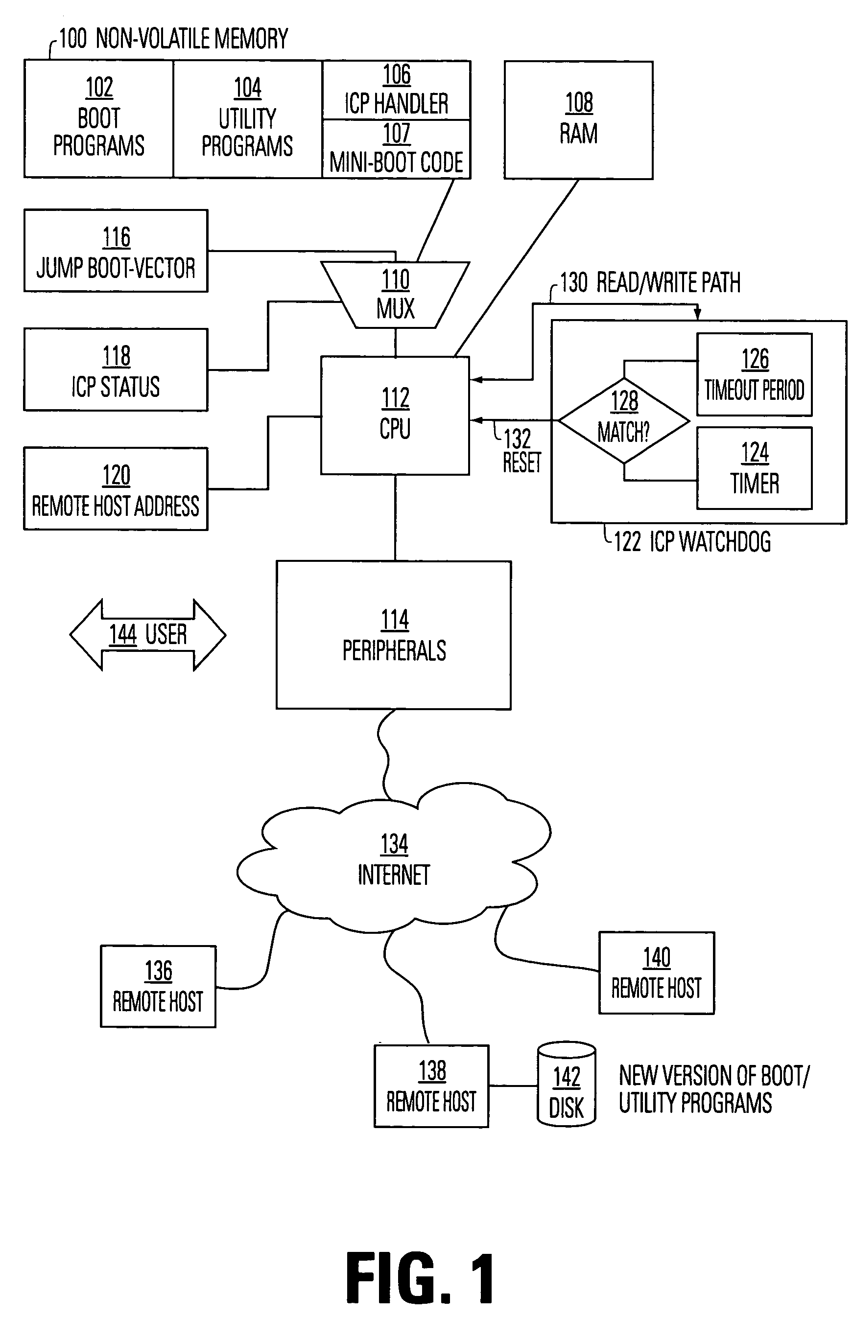
[0053]The present invention yet further provides an architecture for a microcontroller system on an integrated circuit supporting in-circuit programming. This system maintains flexibility in the in-circuit programming process by storing some of the in-circuit programming (ICP) code in flash memory where it can be easily altered using the in-circuit programming process, and storing portions of the ICP code that do not need to be modified in more space-efficient mask ROM cells on the integrated circuit. In particular, ICP code which handles the communication involved in the in-circuit programming process is stored in flash memory so that it may be easily modified to accommodate a number of different communication formats and protocols. Code to implement the erase, program and verify portions of the in-circuit programming process are kept in space-efficient mask ROM cells on the integrated circuit.
[0054]The flash memory array in the present invention is further simplified by implementing the state machine for the erase, program and verify functions of the flash memory in software stored in mask ROM. Timing functions for the erase, program and verify functions, which are typically implemented in hardware, are also implemented in software stored in the mask ROM. The design of the flash memory in the present invention is thereby simplified and the amount of silicon real estate occupied by the flash memory is consequently reduced. In this way, the in-circuit programming architecture according to the present invention effectively maintains flexibility in the in-circuit programming system, while reducing requirements for silicon real estate occupied by the in-circuit programming system.

Problems solved by technology

However, this approach requires special hardware to program the EPROM array before the device is placed in a circuit.
This limits the use of the microcontroller to a relatively narrow range of applications, and makes it difficult to utilize the ICP function in a dynamic communication environment, where the serial port may not match well with the communication channel across which the updated software is provided.
This SPI port has the disadvantage that it is implemented with inflexible program logic; modification of the in-circuit programming technique cannot be accomplished because of the inflexibility of the SPI port.
The Atmel chip has further disadvantages; complicated hardware must be added to the chip for handshaking with the ICP initiator and emulating the erase / program / verify wave forms for the flash memory; the SPI bus is not always the best choice for diverse system applications; extra system logic is required to modify the original reset circuits, which are used by the in-circuit programming algorithms; and complex SPI driver and receiver logic must be attached to the chip.
Reliability can become a problem during in-circuit programming.
The in-circuit programming process can take up to ten minutes, during which time there may be data transmission errors or recording errors.
These errors can be especially troubling if the code which performs the communication with the outside world (handshaking code) is itself modified during the in-circuit programming process.
If this code gets corrupted, the in-circuit programming module may be left without any way of resetting itself or communicating with the outside world.
However, prior art approaches have been inflexible in the in-circuit algorithms used.

Method used


Image

  • Fault-tolerant architecture for in-circuit programming
  • Fault-tolerant architecture for in-circuit programming
  • Fault-tolerant architecture for in-circuit programming

Examples


Embodiment Construction

;© 1996 Macronix International Co., Ltd.;;SFR define.EQUFMCON, 0 × 40 H;Flash Module CONtrolregister.EQUFMTIM, 0 × 41 H;Flash Module TIMingregister;used by s / w to emulate theemulate;the waveform needed forflash operations.EQUdelay1, 0 × fah;Tck = 1 / Fosc (ns);delay1 = (256–2000 / (Tck*12) + 1).EQUdelay2, 01 × 1AH;delay2 = (500000000 / Tck*12 * 65536);Subroutine: Erase full chipERASE:MOVFMCON, #00010010 b;chip eraseMOVFMTIM, #11000000 b;VPP in and CEB is activeLCALLDELAY2 us;delay tVPS or tCES (2 us)MOVFMTIM, #11010000 b;WEB is activeLCALLDELAY1 s;delay tEW (erase time)MOVFMTIM, #11000000 b;disable WEBLCALLDELAY500 ms;delay tER (0.5 s)MOVFMTIM, #00000000 b;clear FMTIMMOVFMCON, #00000000 b;clear FMCONRET;Subroutine: Verify erased byteERASE_VERIFY:MOVFMCON, #00010010 b;verify chip eraseMOVFMTIM, #11000000 b;VPP in, CEB is activeMOVDPTR, #00 H;AddressLCALLDELAY2 us;delay tMS (2 us)MOVFMTIM, #11100000 b;OEB is activeMOVR1, #00 hMOVR0, #00 HNOPNOPLOOP_E:;MOVXA,@DPTR;read FlashCJNEA,#0 × FFH, E...


PUM


Abstract

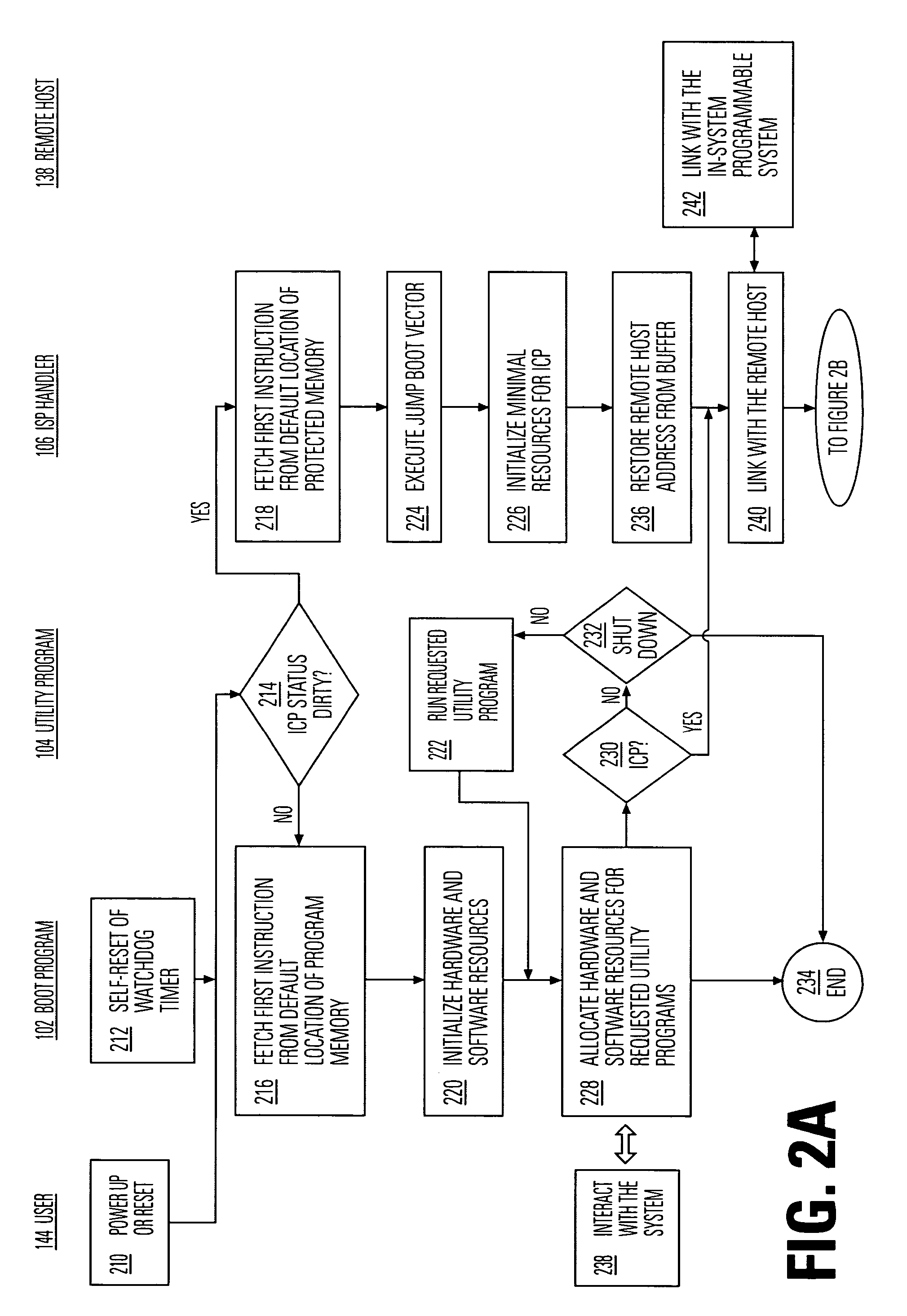
The present invention provides a method and apparatus for providing fault-tolerance for in-circuit programming systems. The invention operates by storing a minimal set of code to initialize the in-circuit programming process in a protected memory so that if the in-circuit programming process fails, the in-circuit programming process can be restarted from the protected memory. This type of fault-tolerance is especially important in systems which allow the code which accomplishes the in-circuit programming to be modified by the in-circuit programming process. One embodiment of the present invention provides a multiplexer to selectively switch between a normal boot code sequence and a protected boot code sequence, as well as a watchdog timer to monitor the in-circuit programming process to determine whether the in-circuit programming process is not progressing properly.

Description

CROSS-REFERENCE TO RELATED APPLICATIONS[0001]This application is a continuation application of application Ser. No. 10 / 097,839 filed 13 Mar. 2002 now abandoned, which is a continuation of application Ser. No. 09 / 925,920 filed 9 Aug. 2001, now U.S. Pat. No. 6,401,221; which is a continuation application of application Ser. No. 09 / 029,118 filed 23 Feb. 1998, now U.S. Pat. No. 6,282,675; which is the national stage filing of International Application No. PCT / US97 / 13848, filed 6 Aug. 1997.[0002]This application is also a continuation-in-part of application Ser. No. 10 / 314,638 filed 9 Dec. 2002 now U.S. Pat. No. 6,842,820; which is a continuation of application Ser. No. 09 / 525,835 filed 15 Mar. 2000, now U.S. Pat. No. 6,493,788; which is a continuation of application Ser. No. 08 / 952,045 filed 3 Oct. 1997, now U.S. Pat. No. 6,151,657; which is the national stage filing of International Application No. PCT / US96 / 17302 filed 28 Oct. 1996.[0003]This application is related to international app...

Claims


Application Information

Patent Timeline
Patent Type & Authority Patents(United States)
IPC IPC(8): G06F11/00G06F11/14H02H3/05
CPCG06F11/1417G06F11/1433
Inventor SUN, ALBERT C.LEE, CHEE H.CHEN, CHANG L.
Owner MACRONIX INT CO LTD
Why Eureka
Try Eureka