Enhancing fluid flow in a stacked plate microreactor

a microreactor and stacked plate technology, applied in the direction of liquid-gas reaction of thin-film type, stationary plate conduit assembly, mixer, etc., can solve the problems of affecting the quality and yield of the desired product, the scaling up process from the laboratory to industrial-scale, and the difficulty of control, so as to achieve the effect of sufficient residence time and maximum control of reaction temperatur

Inactive Publication Date: 2007-07-10
EHRFELD MIKROTECHNIK BTS GMBH
View PDF40 Cites 60 Cited by
  • Summary
  • Abstract
  • Description
  • Claims
  • Application Information

AI Technical Summary

Benefits of technology

[0026]In one embodiment, the simple plates are removably held together in the stack by an applied compressive force. In this embodiment, a housing provides the compressive force, producing a pressure acting on the outer simple plates. The mean surface roughness of the plates is preferably less than about one (1) micrometer, and the simple plates are substantially free of scratches. The pressure is preferably greater than or equal to 300 Newtons per square millimeter, preferably in conjunction with the use of gaskets or O-rings. In another embodiment, the simple plates are permanently joined. When permanently joined, the mean surface roughness of the plates is preferably less than about 5 micrometers. Permanent joining can be achieved using diffusion welding or vacuum soldering. It should be noted that if compressive forces are employed to join the simple plates, the reactor could be readily reconfigured by removing the compressive force, and replacing or adding additional simple plates.
[0027]Preferably the openings in the plurality of intermediate simple plates share common shapes and sizes to the extent possible, to minimize fabrication costs. Preferably, all the simple plates are chamfered at one corner to provide a reference when assembling the simple plates to form the chemical reactor.
[0029]Such stacked plate reactors include a first simple plate comprising a fluid inlet for each different chemical reactant, a fluid outlet for a chemical product, a fluid inlet for a heat transfer media, a fluid outlet for a heat transfer media, a plurality of serially-connected reaction units, and a bottom plate. Each reaction unit is in fluid communication with the first simple plate and comprises a stack of simple plates, each simple plate having at least one opening that extends therethrough, an opening in each simple plate overlapping at least one other opening in an adjacent simple plate thereby forming a plurality of heat exchangers for modifying a temperature of at least one of a chemical reactant and a chemical product, and at least one mixing and reaction channel. Most preferably, each mixing and reaction channel is sandwiched between an upper and a lower heat exchanger to maximize the ability to control a reaction temperature.
[0030]Preferably, each serially-connected reaction unit includes a first heat exchanger for modifying a temperature of a first chemical reactant, and a second heat exchanger for modifying a temperature of a second chemical reactant and for modifying a temperature of a mixing and reaction channel. Also included are at least one mixing and reaction channel that establishes a laminar flow relationship between a first chemical reactant and a second chemical reactant in order to mix a first chemical reactant and a second chemical reactant together via diffusion mixing, and to provide sufficient residence time for initiation of a chemical reaction between a first chemical reactant and a second chemical reactant. In addition, a third heat exchanger is included for modifying a temperature of the mixing and reaction channel.
[0033]Other preferred embodiments in accord with the present invention are directed to stacked plate reactors in which the means for manipulating a flow of fluid in a reactor to achieve a desired result is specifically employed to enable viscous fluids to be processed, while maintaining a substantially equivalent residence time distribution for processing product fluid that has a substantially different viscosity compared to the viscosity of the reactants flowing through parallel fluid paths. In one group of such embodiments, the means comprises an opening having a bifurcated shape formed in at least one simple plate, the bifurcated shape enhancing the residence time distribution for a fluid flowing in at least one bifurcated fluid channel associated with the bifurcated shape.

Problems solved by technology

Often, problems are encountered in scaling up a process from the laboratory to industrial-scale production.
Problems associated with moving from benchscale production to industrial-scale production often involve changes in process conditions between the benchscale environment and the industrial environment.
Variations in other process conditions within a large tank are also more difficult to control, and frequently affect the quality and yield of the desired product.
Another aspect of laboratory development of processes to produce chemical compounds is that often potentially dangerous chemicals are used to create the desired product.
Fires and explosions in research laboratories and concomitant injury to personnel and property are well known risks in the chemical research industry.
The risks are not limited only to research, since industrial chemical production facilities also may experience fires and explosions related to chemical production using dangerous chemicals.
Often, due to the quantities of chemicals used in industrial-scale processes, such accidents are significantly more devastating in an industrial setting than similar accidents in a research setting.
Any accident in such an environment is likely to increase the risk of exposure to hazardous chemicals, and cause significant damage to the laboratory.
A disadvantage of the reactors described by Ashmead stems from the rather expensive and complicated process required for manufacturing the devices.
While silicon wafer technology has advanced to the state that wafers having desired surface features can readily be mass produced, the equipment required is capital intensive, and unless unit production is extremely high, the substantial costs are difficult to offset.
For instance, while forming an opening through a material is relatively easy, forming a groove or channel that penetrates only part way through the material comprising a layer is more difficult, as the manufacturing process must not only control the size of the surface feature, but the depth, as well.
Furthermore, the lateral layout of the reactor described by Bard requires a larger footprint (Basis Area) than a stacked plate reactor.
In Bard's reactor, the more modules added, the larger the footprint of the entire reactor.
In all of these prior art reactors, relatively complicated manufacturing techniques are required.
The manufacture of layers of silicon material requires a large capital investment.
Sintering of a ceramic material requires the precise control of the shrinkage process, or individual components of a desired size cannot be achieved.
When additional modular microreactor units are added, additional systems for reactant supply, heat transfer media supply, and product collection are typically required, which not only increases the complexity of the system, but also requires more space for duplicative fluid systems.
Furthermore, even minor differences in feed rates for some of the duplicate reactor modules can negatively effect product quality.
However, the flow distribution through such an array is not even if the viscosity of the product is significantly different than the viscosities of the reactants.
When such an array is employed to process a reaction whose product has a significantly different viscosity compared to the viscosity of the mixture of the unreacted reactants, broad residence time distributions result in the array due to the fact that the pressure drop in the common reactant distribution channel no longer balances with the pressure drop in the common product collection channel.
This imbalance leads to different residence times being associated with different fluid channels, resulting in an undesirable residence time distribution within the whole reaction unit.
In certain cases, the additional residence time can lead to undesired cross reactions, and even clogging of the “slowest” fluid channels.
Residence time distribution problems of this type can also arise in fluid channels used to direct reactants before mixing, as well as products for collection.
Currently, the prior art does not include such apparatus.

Method used


Image

  • Enhancing fluid flow in a stacked plate microreactor
  • Enhancing fluid flow in a stacked plate microreactor
  • Enhancing fluid flow in a stacked plate microreactor

Examples


Embodiment Construction

Overview

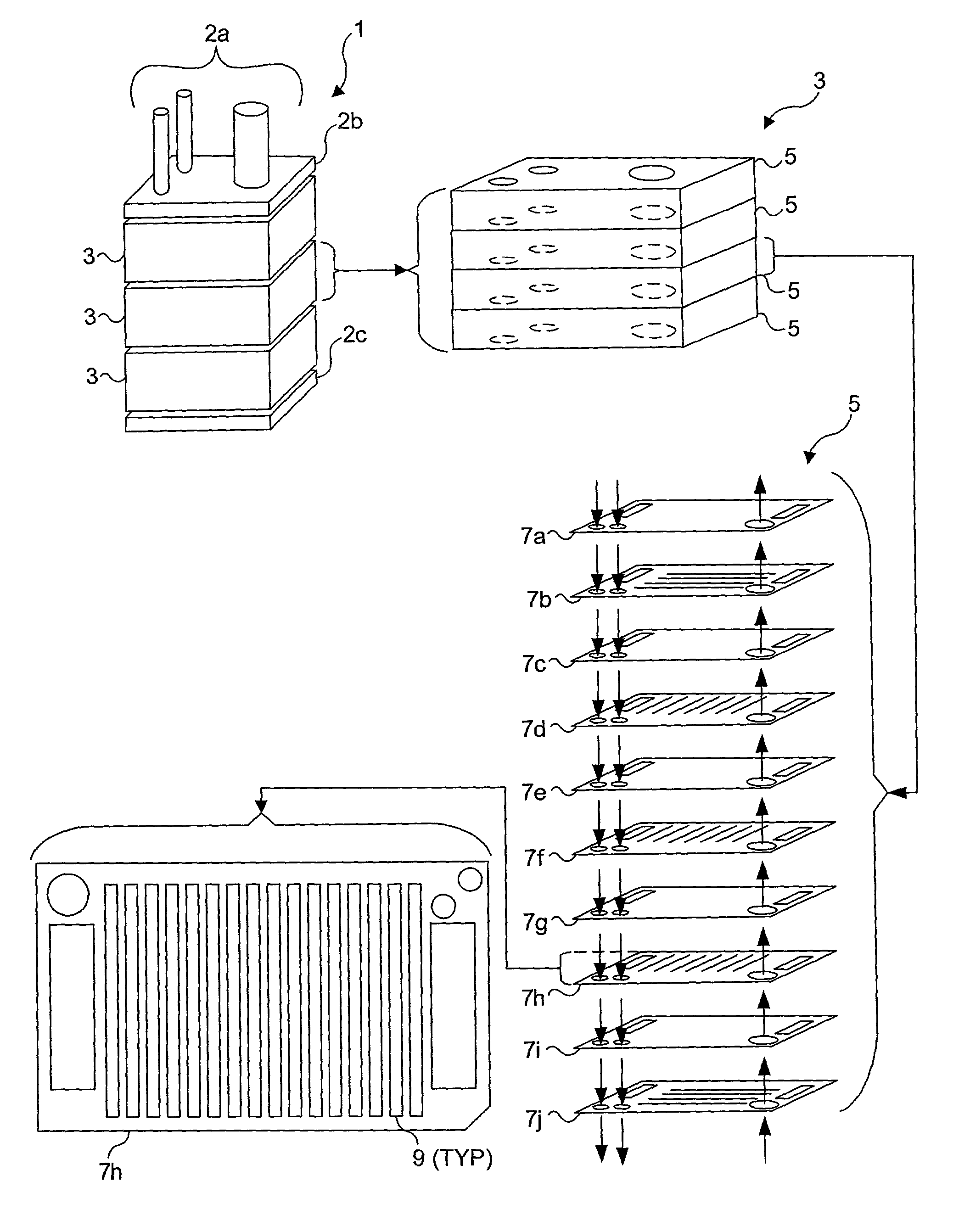
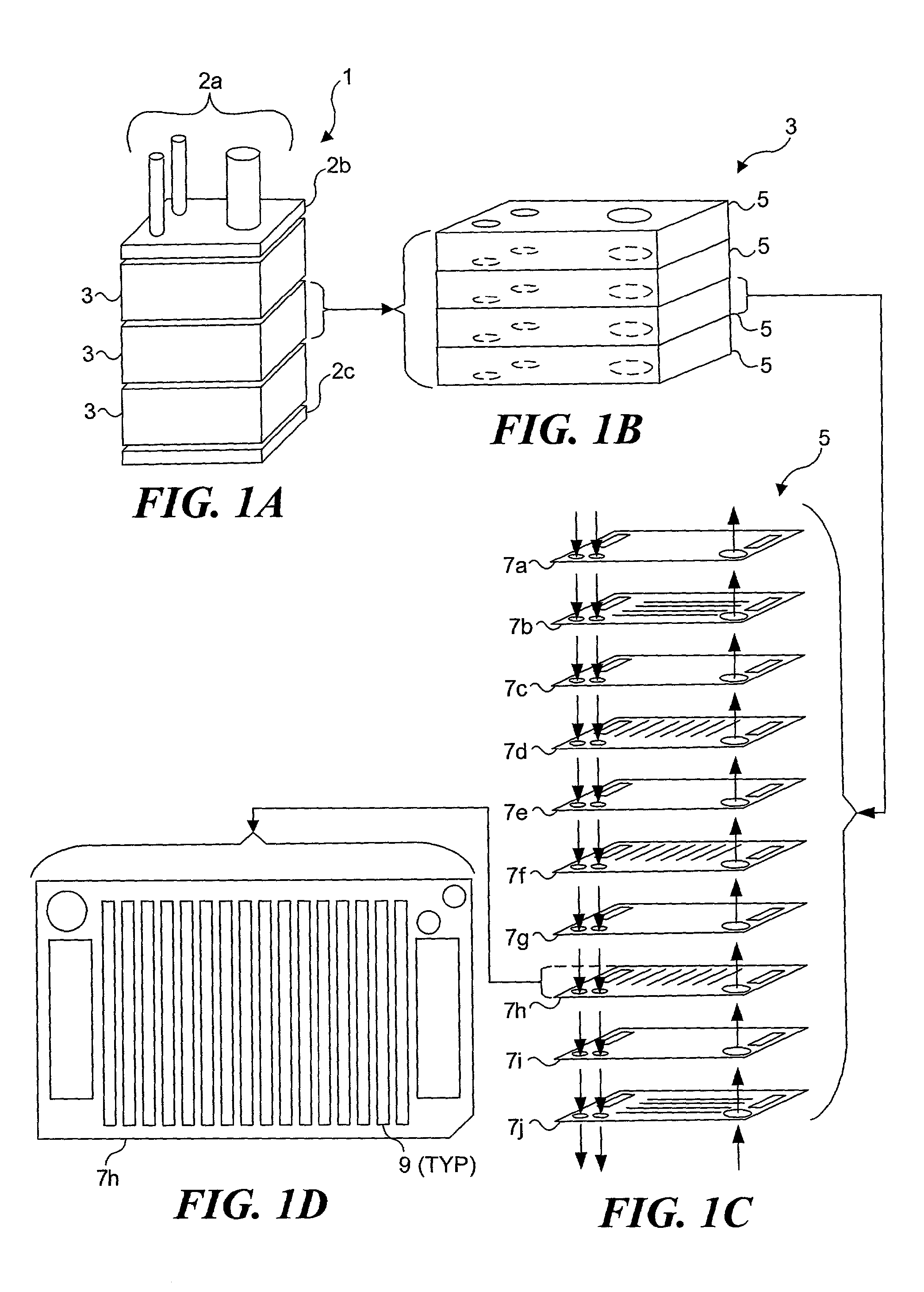
[0116]The present invention relates to internal parallelization in stacked plate reactors employed to produce a chemical product. The term internal parallelization, as applied both to this disclosure and to the claims that follow, should be understood to mean simultaneously addressing a plurality of substantially identical micro-scale processing elements using only a single fluid inlet and a single fluid outlet for each fluid type (i.e., reactant, product, and heat transfer media). These processing elements can include micro-reactor units, fluid processing channels (i.e., channels utilized for thermal treatment and reactant mixing; but not fluid channels utilized for reactant distribution and product collection), heat exchangers and workup units. Workup units (i.e., post processing units) can be employed for quenching a reaction, purification of a product (such as by extraction, distillation, filtration, phase separation, crystallization, or adsorption), and / or for providing...


PUM


Abstract

A stacked plate chemical reactor in which simple plates are stacked together to form the reactor. When openings in adjacent plates are properly aligned, fluid pathways and processing volumes are defined for chemical reactants, heat transfer medium, and a product. In one embodiment of the invention, an n-fold internal array is achieved by providing a first group of simple plates defining a reaction unit that includes bypass fluid channels and reaction fluid channels for each reactant, such that a portion of each reactant is directed to subsequent groups of simple plates defining additional reaction units. A chemical reactor with variable output is obtained in a preferred embodiment by reversibly joining reactor stacks comprising irreversibly joined reaction units, these reaction units consisting of a plurality of simple plates. Other embodiments employ at least one of an array of parallel fluid channels having different widths, bifurcated fluid distribution channels to achieve a substantially even flow equipartition for fluids with varying viscosities flowing within the fluid channels of each reaction unit.

Description

RELATED APPLICATIONS[0001]This application is a continuation-in-part of prior U.S. patent application Ser. No. 09 / 496,999, filed Feb. 3, 2000 now U.S. Pat. No. 6,537,506, priority in the filing date of which is hereby claimed under 35 U.S.C. § 120.FIELD OF THE INVENTION[0002]This invention generally relates to a miniaturized chemical processing apparatus, and more specifically, to a miniaturized chemical processing apparatus assembled from stacked plates that cooperate to provide fluid channels for conveying reactants and other fluids.BACKGROUND OF THE INVENTION[0003]Methods of controlling and optimizing processes for producing chemical compounds are well known. The control of parameters such as temperature, pressure, mixing conditions, relative volumes of reactants, and uses of catalysts are generally well understood. Traditionally, newly discovered chemical compounds and processes involving either the production of such compounds, or processes involving the use of such compounds, ...

Claims


Application Information

Patent Timeline
Patent Type & Authority Patents(United States)
IPC IPC(8): B01J19/00B01F5/06F28D9/02B01F13/00B01F13/10B01F15/06B01J19/24F28D9/00
CPCB01F5/0604B01F13/0064B01F13/0066B01F13/0093B01F13/0094B01F13/1022B01J19/0093B01J19/248B01J19/249F28D9/0093B01F13/0059B01F13/1013B01F15/06B01J2219/00783B01J2219/00804B01J2219/00835B01J2219/00869B01J2219/00871B01J2219/00873B01J2219/00889B01J2219/00961B01J2219/00995B01J2219/00997B01J2219/2453B01J2219/2456B01J2219/246B01J2219/2462B01J2219/2464B01J2219/247B01J2219/2485B01J2219/2486B01J2219/2487B01J2219/2488B01J2219/249B01J2219/2493B01J2219/2495B01J2219/2496B01J2219/2497F28F2210/02F28F2260/02B01F25/422B01F33/3017B01F33/3012B01F33/3039B01F33/304B01F33/30B01F33/813B01F33/81B01F35/90
Inventor GOLBIG, KLAUSAUTZE, VOLKERBORN, PETERDRESCHER, CHRISTIAN
Owner EHRFELD MIKROTECHNIK BTS GMBH
Why Eureka
Try Eureka