

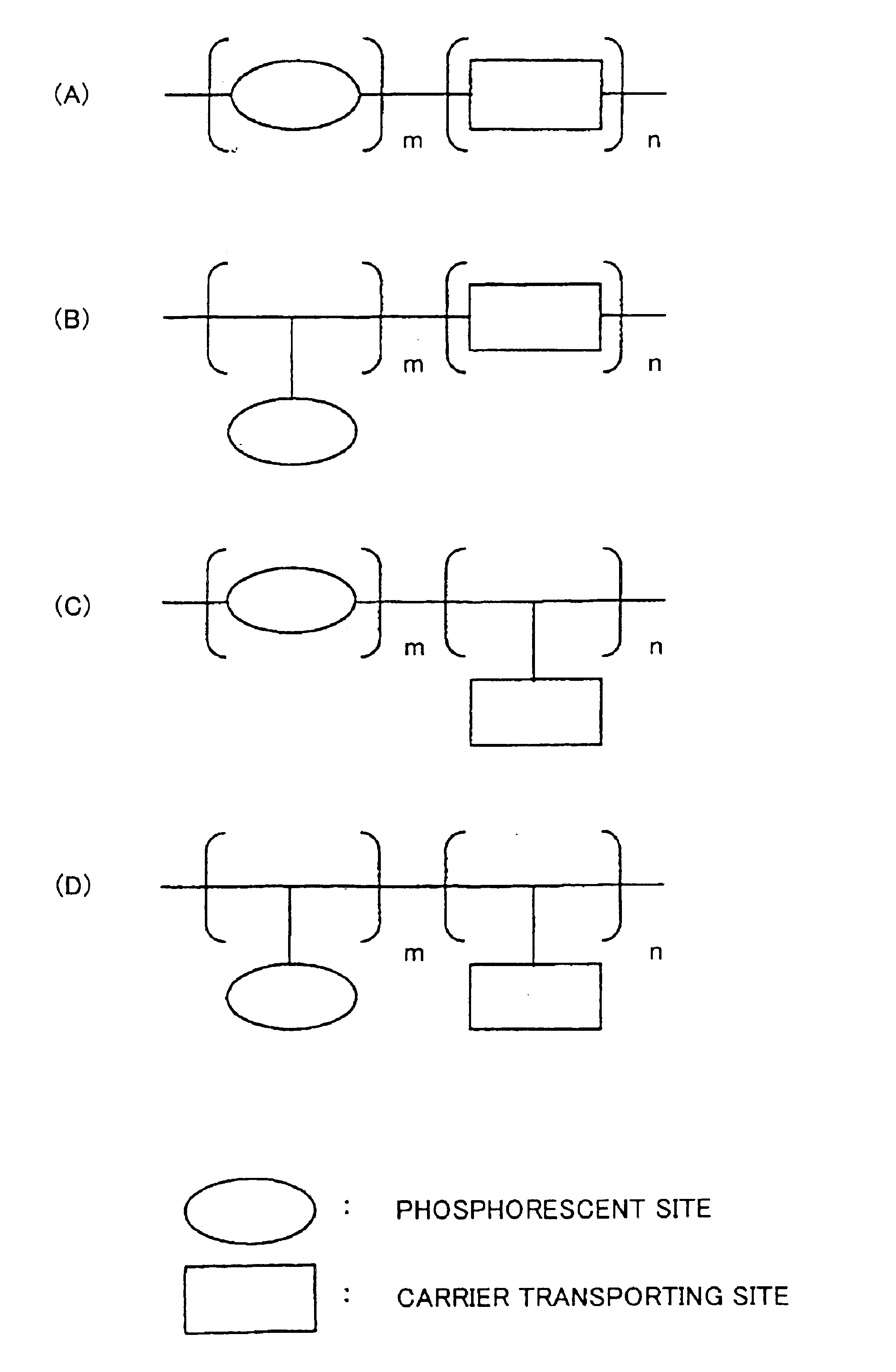
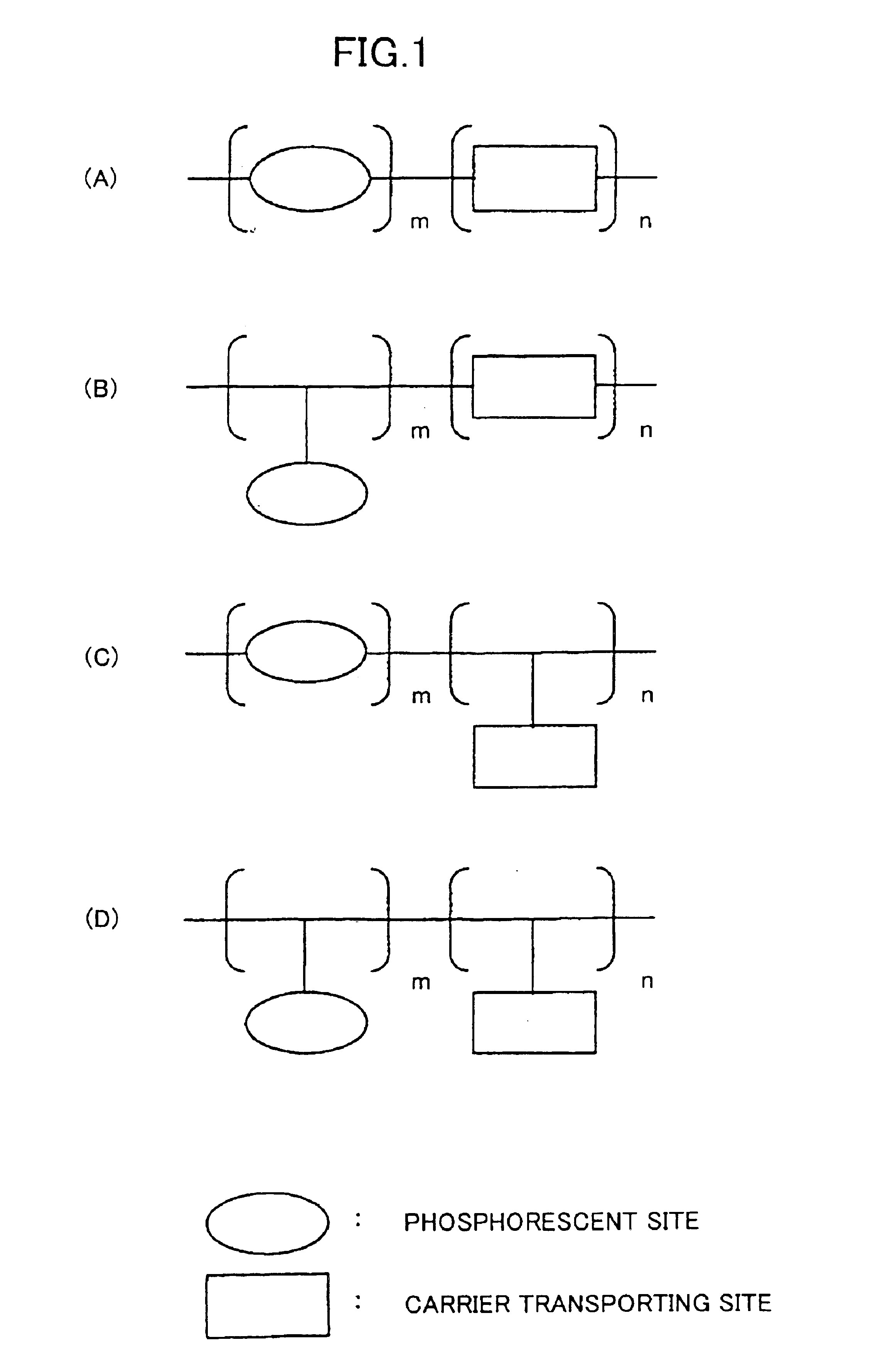
Phosphorescent compound, a phosphorescent composition and an organic light-emitting device
a technology of organic light-emitting devices and phosphorescent compounds, which is applied in the direction of discharge tube luminescnet screens, natural mineral layered products, etc., can solve the problems of insufficient emission efficiency of conventional organic polymer light-emitting devices, and the inability to improve emission efficiency, etc., to achieve high emission efficiency and long service life. , the effect of stable and stabl
- Summary
- Abstract
- Description
- Claims
- Application Information
AI Technical Summary
Benefits of technology
Problems solved by technology
Method used
Image

Examples
example 1-1
[0133]Synthesis of the monomer of the phosphorescent compound; [2-(3-methacrylphenyl)pyridine]bis[2-(3-propionylphenyl)pyridine]iridium(III) (simplified as Ir(MPPy)(PrCOPPy)2 below)
[0134]First, 2-(3-methoxyphenyl)pyridine (MeOPPy) was synthesized according to the usual method of scheme (1).
[0135]Specifically, 3-methoxyphenylmagnesiumbromide was synthesized from 8.98 g (48 mmol) of 3-bromoanisole using Mg in 60 ml of dried tetrahydrofuran (THF). Furthermore, the preceding obtained 3-methoxyphenylmagnesiumbromide was added into the solution in which 6.32 g (40 mmol) of 2-bromopyridine and 0.74 g of [1,2-bis(diphenylphosphino)ethane]dichloronickel(0) (Ni(dppe)Cl2) had been dissolved into 40 ml of dried THF, and reaction was performed for 12 hours at room temperature to obtain 6.03 g (32.4 mmol) of colorless and transparent 2-(3-methoxyphenyl)pyridine (MeOPPy). Identification was performed by CHN elemental analysis, NMR, and IR.
[0136]Next, MeOPPy obtained in scheme (1) and tris(acetyla...
example 1-2
[0141]Synthesis of the phosphorescent compound; [2-(3-methacrylphenyl)pyridine]bis[2-(3-propionylphenyl)pyridine]iridium(III) / N-vinylcarbazole copolymer (simplified as Ir(Mppy) (PrCOPPy)2 / VCz copolymer below)
[0142]According to scheme (5), after 0.222 g (0.25 mmol) of Ir(MPPy) (PrCOPPy)2 complex synthesized in example 1, 0.918 g (4.75 mmol) of N-vinylcarbazole (VCz) (Ir(MPPy) (PrCOPPy)2 and VCz being in molar ratio of 5:95) 0,010 g (0.061 mmol) of 2,2′-azobis(isobutyronitrile) (AIBN), 10 ml of butyl acetate were put into a reactor and replacement with nitrogen was performed, reaction was performed for 10 hours at 80° C.
[0143]After the reaction, the product was thrown into acetone, reprecipitation was performed, and a copolymer was recovered by filtration. Throwing of a solution of the recovered copolymer in chloroform into methanol for reprecipitation was further performed twice for purification and vacuum drying was performed after recovering the precipitation, to obtain 0.946 g of...
example 1-3
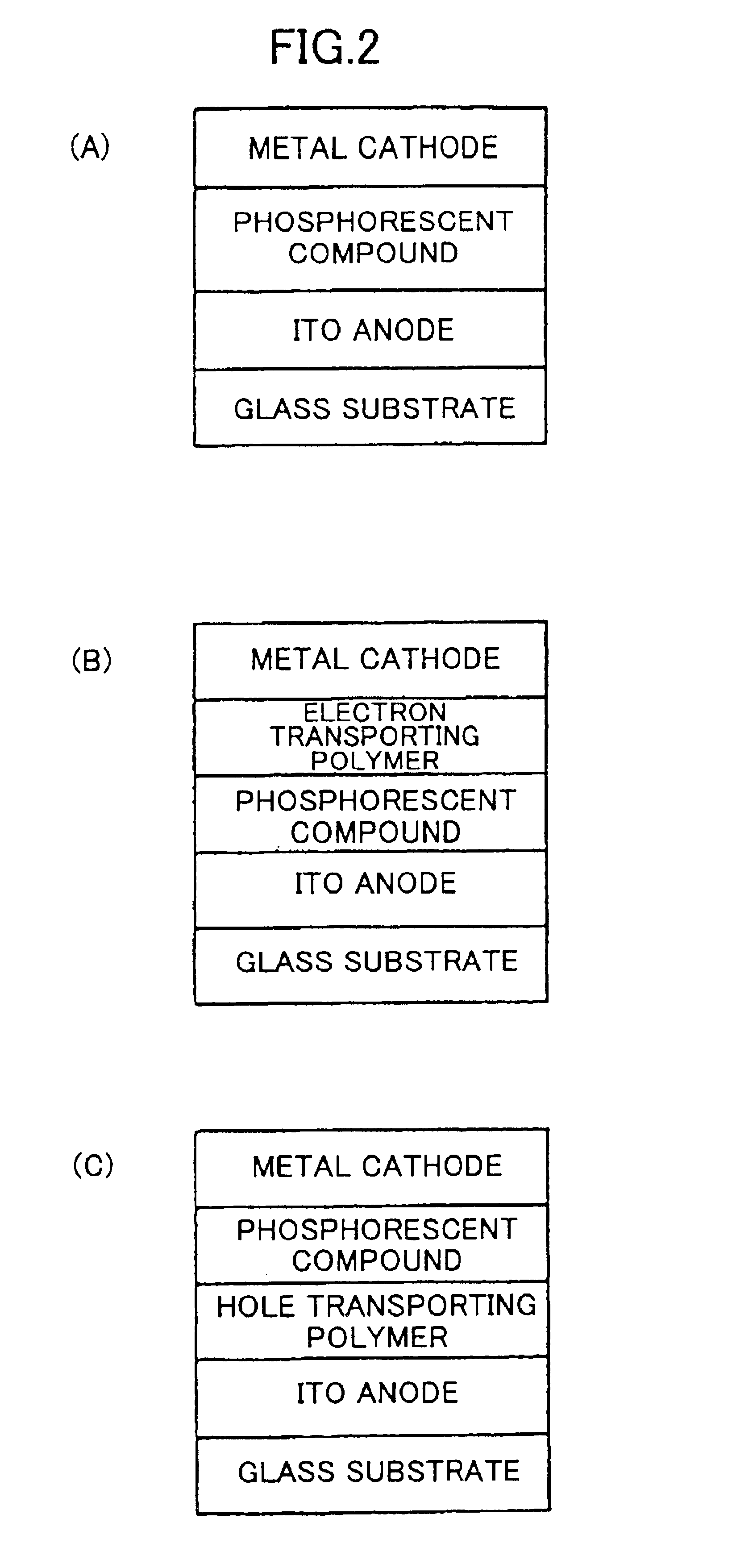
Fabrication of an Organic Light-emitting Device
[0144]A solution of Ir(MPPy) (PrCOPPy)2 / VCz copolymer and an oxadiazole derivative (tBu-PBD) being an electron transporting material in chloroform was prepared. The proportion was 65 percent by weight for Ir(MPPy) (PrCOPPy)2 / VCz copolymer to 35 percent by weight for tBu-PBD. This solution was spin-coated on a glass substrate with indium tin oxide (ITO) being a transparent electrode to form a film with the thickness of 100 nm, and 10 nm of Ca and 100 nm of Al were deposited on it by a vacuum evaporation to provide a cathode. As a positive electrical voltage was applied on the ITO-side of this organic light-emitting device and a negative electrical voltage was applied on the Al-side, green luminescence originating from the iridium complex was observed. The quantum yield of the luminescence was approximately 4%.
PUM
| Property | Measurement | Unit |
|---|---|---|
| atomic number | aaaaa | aaaaa |
| atomic number | aaaaa | aaaaa |
| atomic number | aaaaa | aaaaa |
Abstract
Description
Claims
Application Information