
Thin film composite electrolyte

a composite electrolyte and thin film technology, applied in the direction of non-aqueous electrolyte cells, ceramics, cell components, etc., can solve the problems of low ion flux, unsupported electrolyte tubes of the prior art can typically not be optimized for high flux, and cell made by conventional methods, etc., to achieve excellent bonding between the two layers

Inactive Publication Date: 2007-08-14
TRANS IONICS CORP
View PDF24 Cites 10 Cited by
  • Summary
  • Abstract
  • Description
  • Claims
  • Application Information

AI Technical Summary

Benefits of technology

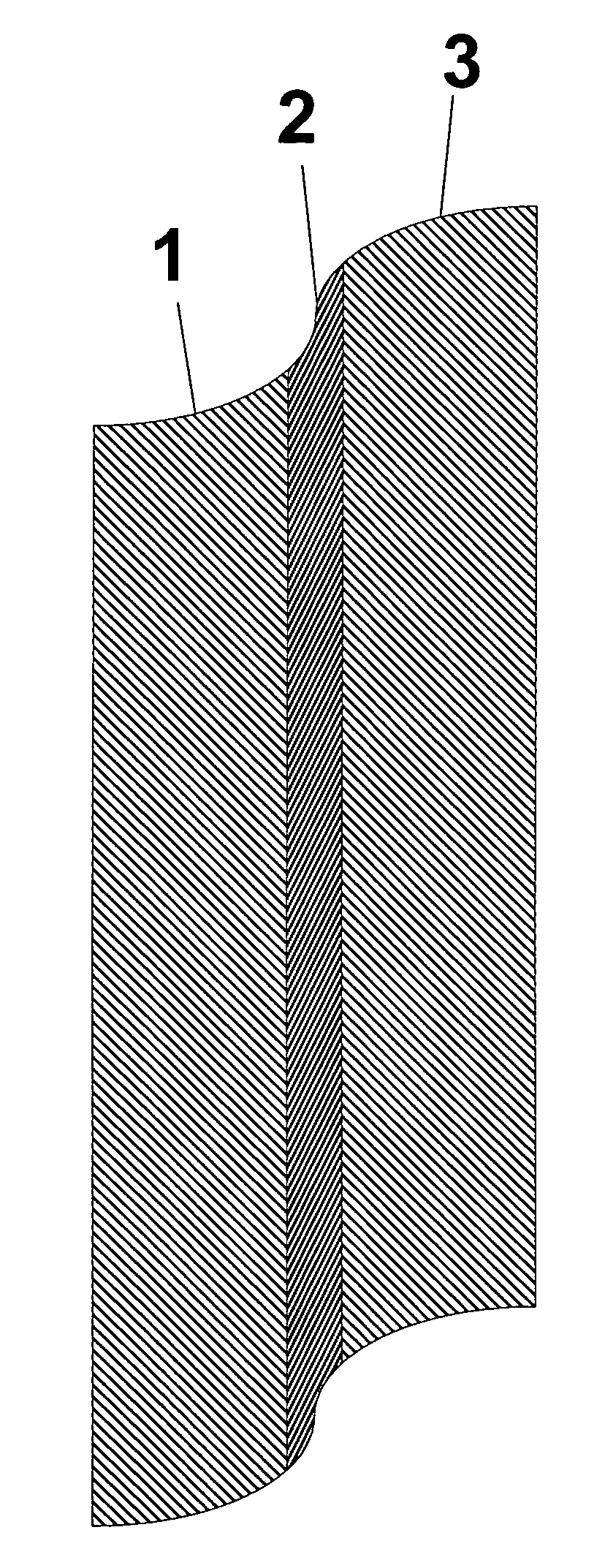
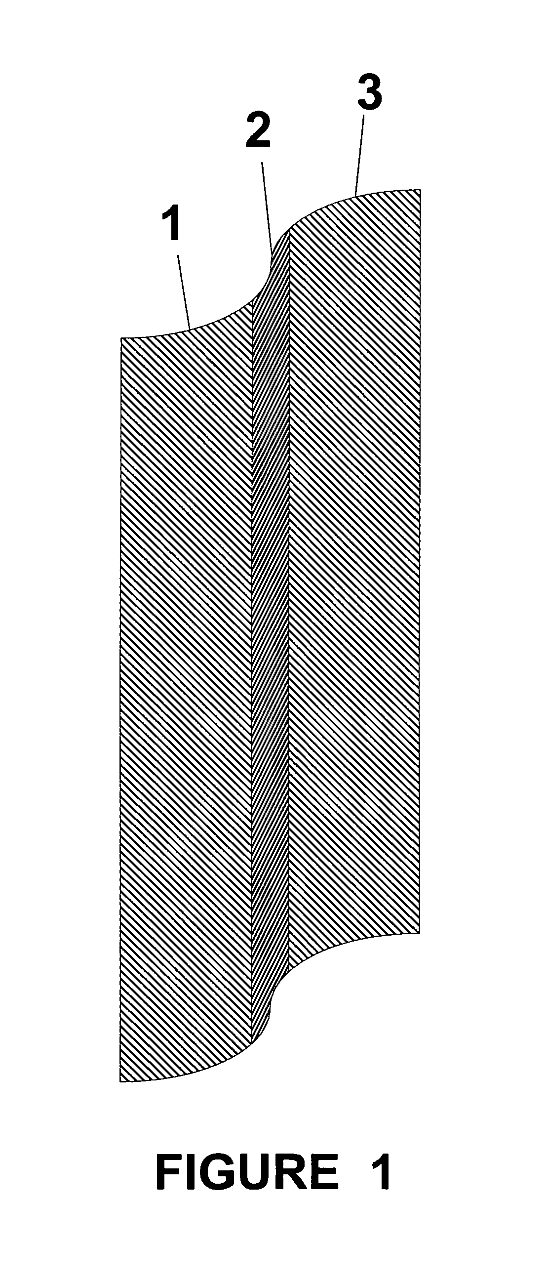
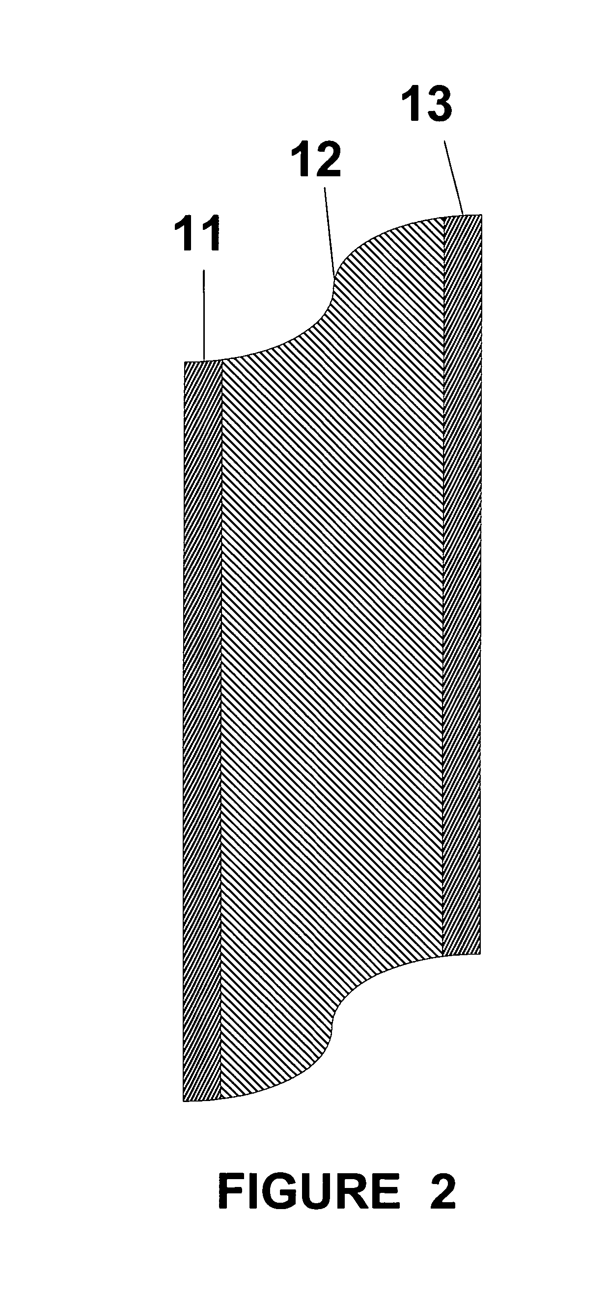
[0020]The electrolyte of the present invention, in its preferred structure, is a supported thin film composite forming a sandwich-like structure of at least three layers, with two exterior layers and an interior layer. While it is possible to create such films as two layer structures (i.e., asymmetric in nature), it has been found that these electrolytes are subject to distortion due to thermal and mechanical stresses that occur during sintering, and that such distortions do not occur for symmetric configurations. To minimize distortions, it is preferred that the sandwich have a center layer and two exterior layers symmetric with respect to the center, the exterior layers having substantially the same thickness, with a variation of up to 15% in the exterior layers. Further, the preferred geometry of the structure of the present invention is planar though it is possible to make the electrolyte of the present invention in tubular form. Two different preferred configurations of the three layers for the electrolyte are described. In each configuration, there is at least one thin, dense layer less than about 100 microns in thickness and preferably less than 50 microns in thickness that is the functional electrolyte layer. The term “dense” is used to mean non-porous, however, the dense layer must be ionically conductive with respect to one of the charged reactants (generally sodium in a sodium / sulfur cell), generally through a diffusion process. For the sodium sulfur battery application a preferred material for the dense layer is β″-Al2O3. Depending on the configuration selected, it is supported on a second layer that is microporous or between two second layers that are microporous, so that reactants can flow to the electrolyte surface as necessary. The thicker microporous layer gives mechanical strength to the composite (herein, “porous” or “microporous” layer refers to an effective porosity and permeability that will allow an effective flow of anodic or cathodic reactants through the layer).
[0021]A feature of the preferred embodiment of the present invention is that this microporous structure is also β″-Al2O3. By constructing the electolyte in this manner, there is no difference at all in coefficient of thermal expansion between the thin, dense layer(s) and the microporous support layer(s). Further, bonding between the two layers is excellent.

Problems solved by technology

There are several inherent disadvantages to cells made by conventional methods.
One disadvantage is that electrolytes made from materials such as β″-Al2O3 have low ion flux, because the electrolyte must be thick enough to also provide mechanical support.
So, while it is generally known that thinner electrolytes have higher ion flux, these unsupported electrolyte tubes of the prior art can typically not be optimized for high flux because of the limitations of their mechanical strength.
Another disadvantage of conventional methods results from forming the electrolyte as tubes on mandrels (typical of the electrophoretic deposition method) because there is a limit on the minimum diameter of the tube and also on its maximum length.
This, in turn, limits the surface area to volume ratio, and thus the energy density, of the resulting electrochemical cell.
For example, sodium-sulfur cells made by conventional techniques have relatively low surface area to volume ratios; and, consequently, they have lower energy densities than desired.
A second concern is that none of the listed refractory ceramic supports are electrically conductive, thereby limiting the configuration of a sodium-sulfur cell made by this process to one in which the anode reactant is on the support side.
This may be because of the significant mismatch in CTE between NASICON (˜1×10⁻⁶ / ° C.) and most microporous substrates.
The conductive dense layer is coated on the substrate (plasma or slurry spraying, or granular deposition), and sintered to a final temperature between 1,500 to 1,800° C. Unfortunately, such an asymmetric two layer composite is subject differential shrinkage in the sintering process, making the composition unreliable as a structural material.

Method used


Image

  • Thin film composite electrolyte
  • Thin film composite electrolyte
  • Thin film composite electrolyte

Examples


example 3

ATION, DENSE LAYER

[0051]Into a small (˜1 pt) mill jar was added ˜215 g ¼″ YSZ cylindrical grinding media. To that was added 0.87 g menhaden fish oil (dispersant), 33.41 g mixed xylenes, 33.42 g anhydrous ethanol and 43.40 g hot (about 120° C.) (β″-Al2O3 from Example 1). The mill jar was sealed and the mixture milled on a roll mill at 60 rpm for 24 hours. To this was then added 3.48 g polyvinylbutyral (binder) and 1.75 g butyl benzyl phthalate (plasticizer). The mixture was further milled at 60 rpm for 24 hours. The slip was then strained to remove grinding media and de-aired under a slight vacuum (˜680 torr) to remove entrained air bubbles. This slip was designated SLIP-026.

example 4

ATION, DENSE LAYER

[0052]SLIP-026 from Example 3 was used to cast tapes of different thickness. Tapes of 2 mils, 3 mils and 4 mils were cast onto silicone coated Mylar using a 10″ Gardner BYK casting knife with an adjustable gap. Tapes were dried on a heated plate at 40° C. and stored in an evacuated container to minimize moisture uptake.

example 5

ATION, MICROPOROUS LAYER

[0053]Into a small beaker was placed 4.5 g attrition milled rice hulls (−325 mesh), 13.50 g unmilled rice hulls (−325 mesh) and 42.00 g β″-Al2O3 (RCS-022 from Example 2). The powders had been previously dried in an oven at 110° C. for 24 hours to remove moisture. The powders were mixed with a spatula until visually homogeneous and added to a small mill jar containing ˜215 g ¼″ YSZ cylindrical milling media. To this was added 1.20 g menhaden fish oil dissolved in 26.40 g mixed xylenes and 26.40 g anhydrous ethanol. The mill jar was sealed, shaken vigorously to mix the components and milled on a roll mill at 60 rpm for 24 hours. To this jar was then added 4.81 g polyvinyl butyral, 3.60 g butyl benzyl phthalate and 3.63 g polyalkylene glycols (plasticizer). The contents were milled for another 24 hours at 60 rpm on a roll mill. The grinding media were strained out and the slip was deaired under a slight vacuum. This slip was designated SLIP-029.


PUM

PropertyMeasurementUnit
temperatureaaaaaaaaaa

Abstract

The invention is a thin film composite solid (and a means for making such) suitable for use as an electrolyte, having a first layer of a dense, non-porous conductive material; a second layer of a porous ionic conductive material; and a third layer of a dense non-porous conductive material, wherein the second layer has a Coefficient of thermal expansion within 5% of the coefficient of thermal expansion of the first and third layers.

Description

STATEMENT REGARDING FEDERALLY SPONSORED RESEARCH OR DEVELOPMENT[0001]The United States Government has rights in this invention pursuant to Contract No. DE-FG03-01ER83317 between the United States Department of Energy and Trans Ionics Corporation.BACKGROUND OF THE INVENTION[0002]1. Field of the Invention[0003]The present invention relates to thin film composite electrolyte structures that are preferably ionically conductive and are therefore suitable for use in electrochemical cells, such as secondary batteries based on sodium and sulfur.[0004]2. Related Art[0005]Solid, ionically conductive electrolyte components are utilized in high temperature electrochemical cells, such as secondary batteries based on sodium and sulfur or sodium and a metal chloride. Such electrochemical cells are typically comprised of: a) a liquid anodic reactant; b) a liquid cathodic reactant; and c) a solid electrolyte component that separates the cathode from the anode and that is permeable by either ions fro...

Claims


Application Information

Patent Timeline
Patent Type & Authority Patents(United States)
IPC IPC(8): H01M2/14H01M6/04H01M6/18H01M10/39H01M50/403H01M50/431H01M50/457
CPCB32B18/00B82Y30/00H01M10/3927C04B35/113C04B35/6261C04B35/6264C04B38/00H01M2/145H01M2/1646H01M2/1686C04B35/10C04B38/0054C04B38/0675C04B38/068H01M2300/0094H01M2300/0074H01M10/3981C04B2111/00612C04B2111/00853C04B2235/3203C04B2235/3206C04B2235/5445C04B2235/5454C04B2235/6025C04B2235/6562C04B2235/6565C04B2235/6567C04B2237/343C04B2237/586C04B2237/588C04B2237/704Y02E60/10H01M50/403H01M50/431H01M50/457
Inventor SCHUCKER, ROBERT C.
Owner TRANS IONICS CORP
Learn More