
System, method, and apparatus for continuous synthesis of single-walled carbon nanotubes

a single-walled carbon nanotube and synthesis technology, applied in chemical/physical/physical-chemical processes, chemical/physical/physical-chemical processes, coatings, etc., can solve the problems of achieve rapid resistance-heating of feedstock, localized directional control of energy, and high-performance structures

Inactive Publication Date: 2007-08-28
LOCKHEED MARTIN CORP
View PDF28 Cites 46 Cited by
  • Summary
  • Abstract
  • Description
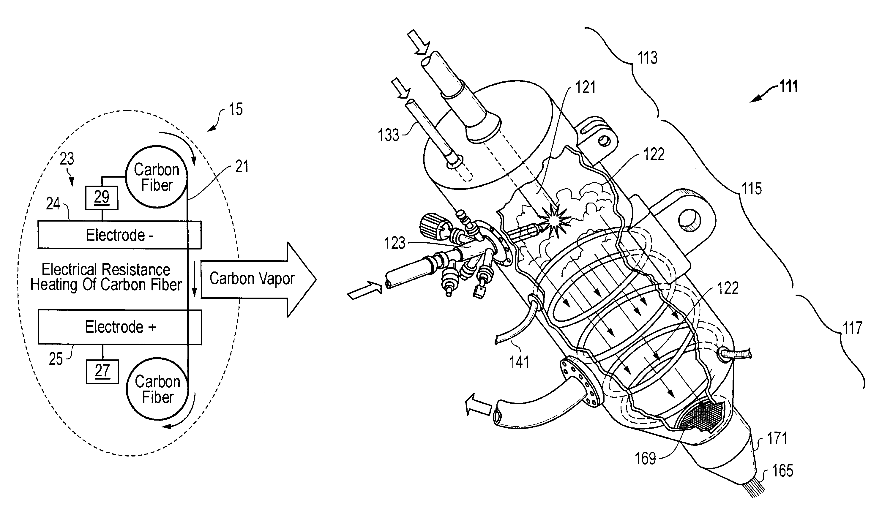
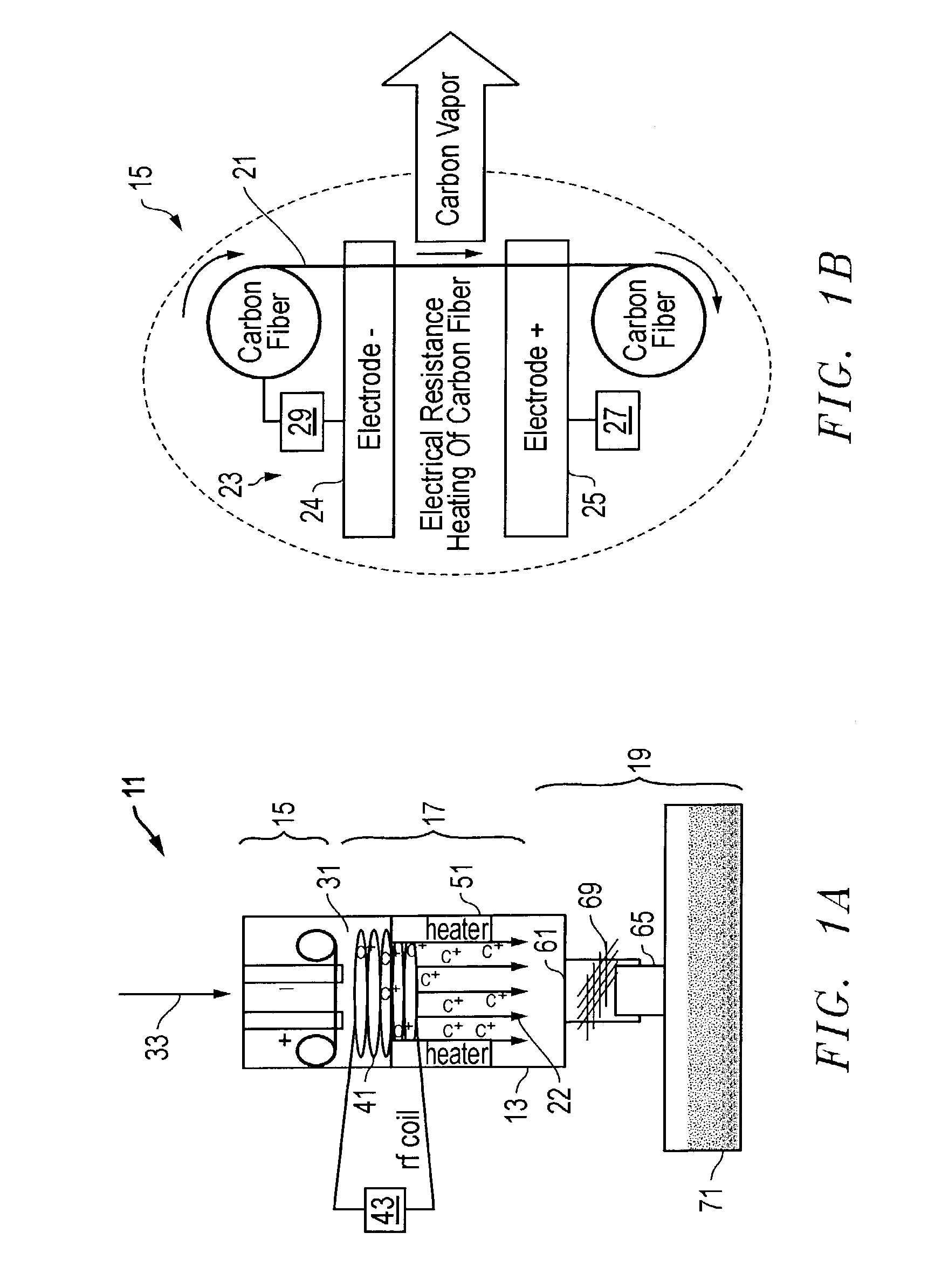
  • Claims
  • Application Information

AI Technical Summary

Benefits of technology

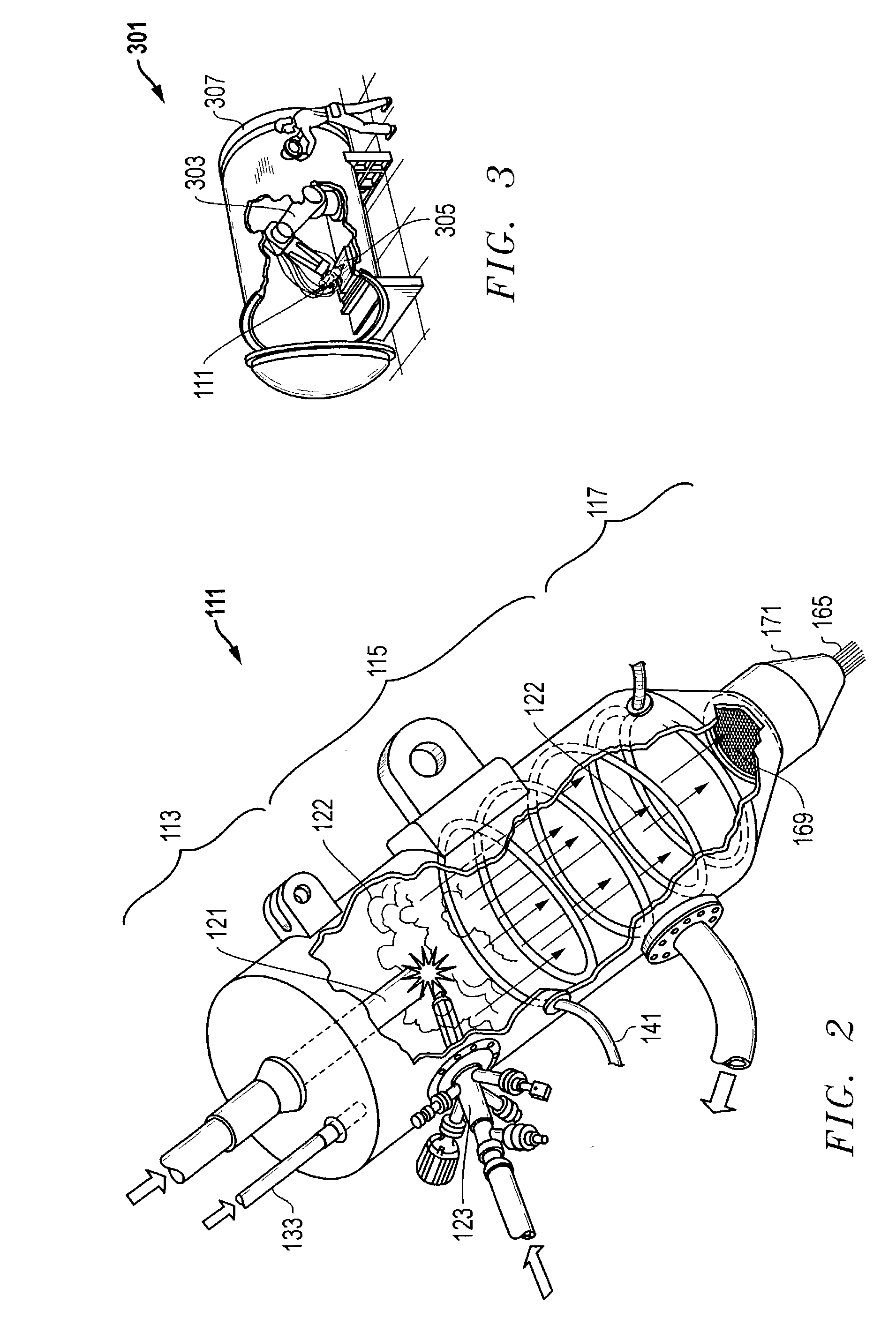
[0008]One advantage and application of the present invention is the continuous, large scale production of single wall carbon nanotubes for manufacturing high performance structures. This method is superior to prior art processes because it provides for (i.) the continuous generation of carbon plasma, (ii.) stabilization of the carbon plasma for homogenization of the reactant mixture and transport of a high concentration of carbon plasma to the product formation zone, and (iii.) a continuous operation, flow-through reactor design. In addition, the entire apparatus is designed so that it can be mounted vertically, such that continuous deposition of product can be precisely applied to a structure using an overhead robotic arm.
[0009]The initiation of the carbon plasma may be accomplished by several methods. One option is vaporization of a resistively-heated graphite element to create a thermal plasma. Carbon or graphite feedstock, which are readily available from commercial suppliers as rod stock, fiber, or in a special-designed geometry, is continuously fed over two oppositely-charged electrodes. Low voltage, high current, electric power is then passed through the feedstock. This results in rapid resistance-heating of the feedstock. The electric power is regulated by feedback control from an ultra-high temperature pyrometer, which measures the element temperature in order to maintain a peak temperature of around 3000° C. The reactor is closed and sealed with a reduced pressure inert atmosphere of continuously-flowing inert gas. By controlling the feed rate of the feedstock, the pressure of the inert gas, and the electric power level, partial vaporization of the feedstock is controlled to a level such that the there is enough carbon remaining to allow a continuous line feed.
[0010]Another method for generating the carbon plasma is to vaporize the feedstock with an electron beam. This method uses an e-beam focused on, for example, a graphite feedstock to generate a carbon plasma. This design allows localized directional control of the energy and efficient energy transfer because of the highly conductive nature of the graphite.
[0012]The second step in the process of the present invention is plasma stabilization. Classical chemical engineering reactor design specifies that reactants should form a homogeneous mixture for optimization of product yield, purity, and reaction rate. The stabilization step has been completely ignored in the processes reported in the open literature to date. This stabilization step homogenizes the plasma energy density and concentration, leading to a more efficient reactor. The stabilization of the carbon plasma is achieved using inductively coupled radio frequency (rf) energy or microwave (mw) energy from a wave guide. The power and frequency are controlled such that the carbon plasma remains stable in the vapor phase. Electrical resistance heaters also can be added inside the reactor to maintain a chamber temperature of up to 1700° C. This additional thermal energy may be used to reduce the required rf or mw energy needed to stabilize the carbon plasma, and to also promote a higher concentration of carbon vapor in the reactor. Stabilization of the plasma occurs immediately downstream from the generated plasma.

Problems solved by technology

This results in rapid resistance-heating of the feedstock.

Method used


Image

  • System, method, and apparatus for continuous synthesis of single-walled carbon nanotubes
  • System, method, and apparatus for continuous synthesis of single-walled carbon nanotubes
  • System, method, and apparatus for continuous synthesis of single-walled carbon nanotubes

Examples


Embodiment Construction

[0025]Referring to FIGS. 1-8, a system, method, and apparatus for producing single-walled carbon nanotubes (swcnt) in a continuous manner is shown. As will be described in greater detail below, some of the embodiments of the present invention use a three-step process of carbon plasma generation, plasma stabilization, and product deposition, all of which are scalable to large, industrial volume production levels. For example, FIGS. 1a and 1b depict one embodiment of an apparatus 11 for producing single-walled carbon nanotubes. Apparatus 11 comprises a continuous operation, flow-through reactor 13 having an initial region 15 (FIG. 1b), a plasma stabilization region 17, and a product formation region 19. The product formation region 19 is located immediately downstream from the plasma stabilization region 17. A feedstock 21 is located in the initial region 15 and is designed and adapted to be continuously supplied to the reactor 13. The feedstock 21 may comprise many different types an...


PUM

PropertyMeasurementUnit
Temperatureaaaaaaaaaa

Abstract

A process for producing single-walled carbon nanotubes in a continuous manner includes carbon plasma generation, plasma stabilization, and product deposition. The plasma is generated by electrical resistance heating or electron beam vaporization of feedstock. The plasma is stabilized with radio frequency energy from inductance coils and with electrical resistance heaters in the reactor. Stabilization homogenizes the plasma energy density and concentration, leading to a more efficient reactor. Finally, a transition metal catalyst and associated catalyst support are used to form the end product. The formation region may have variations of geometry and supporting equipment that will affect the rate and purity of the swcnt production. The formation region is immediately downstream from the plasma stabilization region. In addition, the entire apparatus is designed so that it can be mounted vertically such that continuous deposition of product can be applied with precision using an overhead robotic arm.

Description

[0001]This patent application is related to U.S. patent application Ser. No. 10 / 455,495, entitled, Pure Carbon Isotropic Alloy of Allotropic Forms of Carbon Including Single-Walled Carbon Nanotubes and Diamond-Like Carbon, which was filed concurrently herewith and is incorporated herein by reference.BACKGROUND OF THE INVENTION[0002]1. Technical Field[0003]The present invention relates in general to an improved process for manufacturing carbon nanotubes and, in particular, to an improved system, method, and apparatus for continuous synthesis of single-walled carbon nanotubes.[0004]2. Description of the Related Art[0005]Currently, production of single-walled carbon nanotubes (swcnt) is substantially limited to an experimental or laboratory scale with the largest production rates being on the order of only grams per day. There are several different processes that are used for swcnt production, such as laser ablation methods, arc discharge methods, and chemical vapor deposition (CVD) me...

Claims


Application Information

Patent Timeline
IPC IPC(8): C23C16/00B01J19/08C01B31/02D01F9/12
CPCB01J19/087B82Y30/00B82Y40/00C01B31/0233C01B31/024D01F9/12Y10S977/777B01J2219/0839B01J2219/0879B01J2219/0894B01J2219/0898C01B2202/02Y10S977/742Y10S977/773Y10S977/75B01J2219/0809C01B32/162C01B32/164
Inventor GARDNER, SLADE H.
Owner LOCKHEED MARTIN CORP
Learn More