Methods for resist stripping and other processes for cleaning surfaces substantially free of contaminants

a technology of resist stripping and other processes, which is applied in the direction of cleaning using liquids, grinding machine components, manufacturing tools, etc., can solve the problems of high cost per wafer, high capital cost, and general unsuitability of wet chemistries, and achieve high vacuum level and prevent loss of vacuum

Inactive Publication Date: 2007-11-20
NANOCLEAN TECH
View PDF85 Cites 12 Cited by
  • Summary
  • Abstract
  • Description
  • Claims
  • Application Information

AI Technical Summary

Benefits of technology

[0006]Integrated, preferably all dry systems and methods in accordance with the present invention can eliminate problems associated with current conventional systems. The present invention also provides technological, environmental as well as economical advantages over such conventional systems. Such advantages include: more effective cleaning by performing all processes in a vacuum environment; using an all dry method which is able to penetrate high aspect ratio vias and trenches due to lower surface tension than liquid; combining chemical and physical mechanisms; lowered capital costs by reducing the number of the pieces of equipment required to accomplish the desired processing; a smaller footprint for the equipment, which tends to take up less space and reduces real estate cost, etc.; less human intervention and training than with multi-equipment conventional systems; lower costs of ownership and per article processing due to the elimination of many costly solvents; increased safety to both humans and the environment due to the elimination of many hazardous chemicals; higher yield due to the elimination of wet processes that negatively affect the materials used; higher throughput due to, for example, the elimination of article transport processes from one piece of equipment to the next and due to the elimination of the article drying process.
[0015]In another aspect of certain preferred embodiments in accordance with the present invention, the cryogenic spray assembly preferably is enclosed inside the cryogenic vacuum chamber while the slide mechanism and drive motor are outside the vacuum chamber. In such embodiments, the cryogenic spray assembly shaft preferably is the only assembly part that is enclosed inside the cryogenic vacuum chamber and it penetrates the vacuum chamber somewhere above the position of the article to be cleaned, to allow the cryogenic spray nozzle to sweep over it. The cryogenic spray medium preferably enters the vacuum chamber to the nozzle thru a shaft that is connected to an all metal flexible tube to allow the movement of the shaft during the sweeping process, where the nozzle will be sliding from the beginning of the article to be cleaned until the end of that article. The opening from where the shaft enters the vacuum chamber preferably is equipped with multiple O-rings and plates to prevent loss of vacuum from the chamber and maintain high vacuum level inside the chamber.

Problems solved by technology

Wet chemistries generally are not desirable due to non-uniformities, selectivity to exposed layers and incomplete resist removal because of mass transport and surface tension associated with the solutions.
For example, there tends to be a high capital cost due to the multiple pieces of equipment that are required.
There also tends to be a high cost per wafer for the cleaning process due to the price of chemicals and chemical disposal, which often involves the use of hazardous chemicals.
Also, wet processes tend to affect material properties such as via corrosion of metal, particularly with copper, and changes in dielectric constant value, particularly with low-k dielectric materials.
In addition, in conventional methods semiconductor wafers typically leave the vacuum environment after photoresist stripping and prior to wet cleaning.
The exposure to atmospheric air often causes an oxide layer to form, which increases the level of difficulty of cleaning.

Method used


Image

  • Methods for resist stripping and other processes for cleaning surfaces substantially free of contaminants
  • Methods for resist stripping and other processes for cleaning surfaces substantially free of contaminants
  • Methods for resist stripping and other processes for cleaning surfaces substantially free of contaminants

Examples


Embodiment Construction

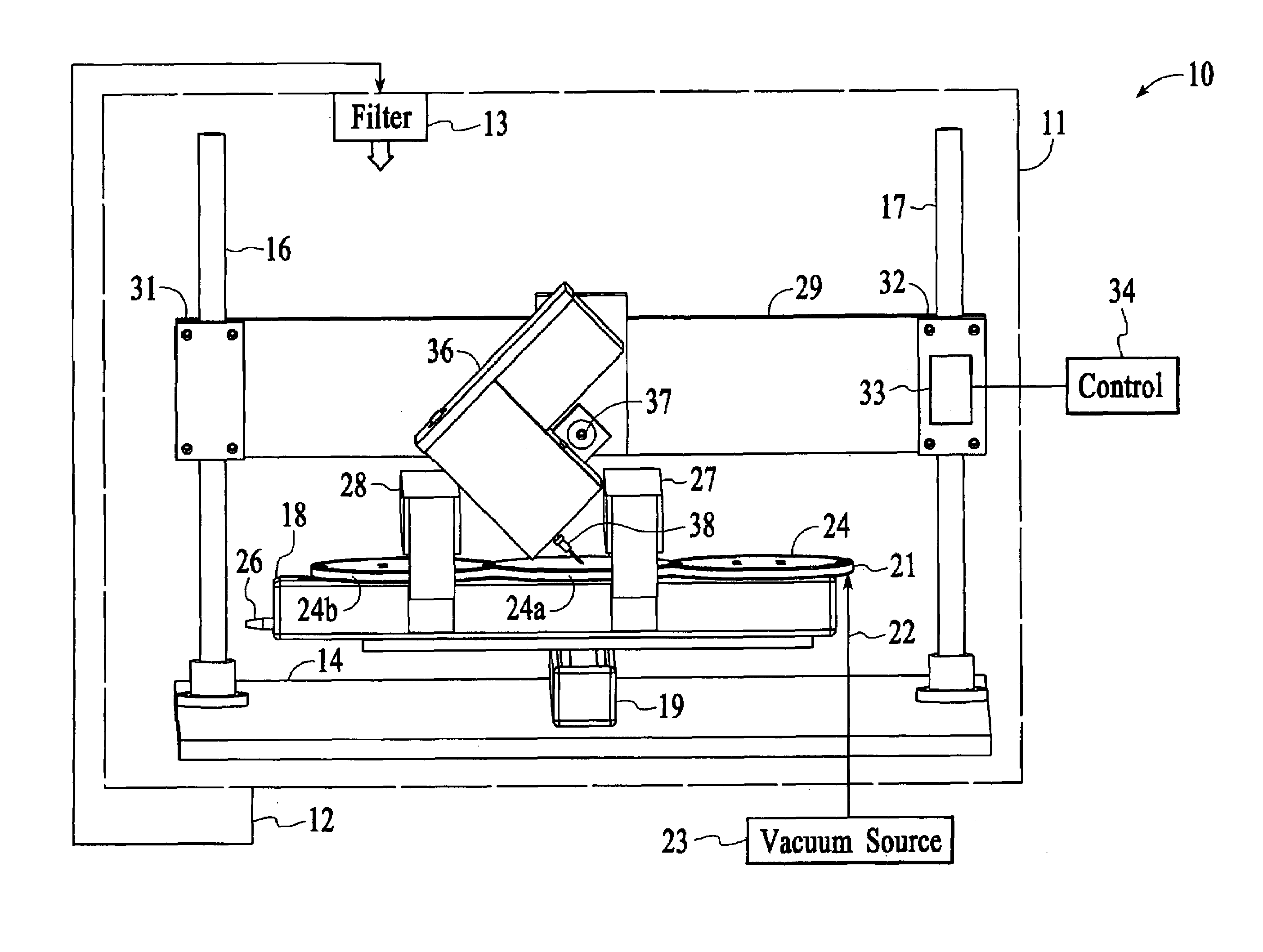
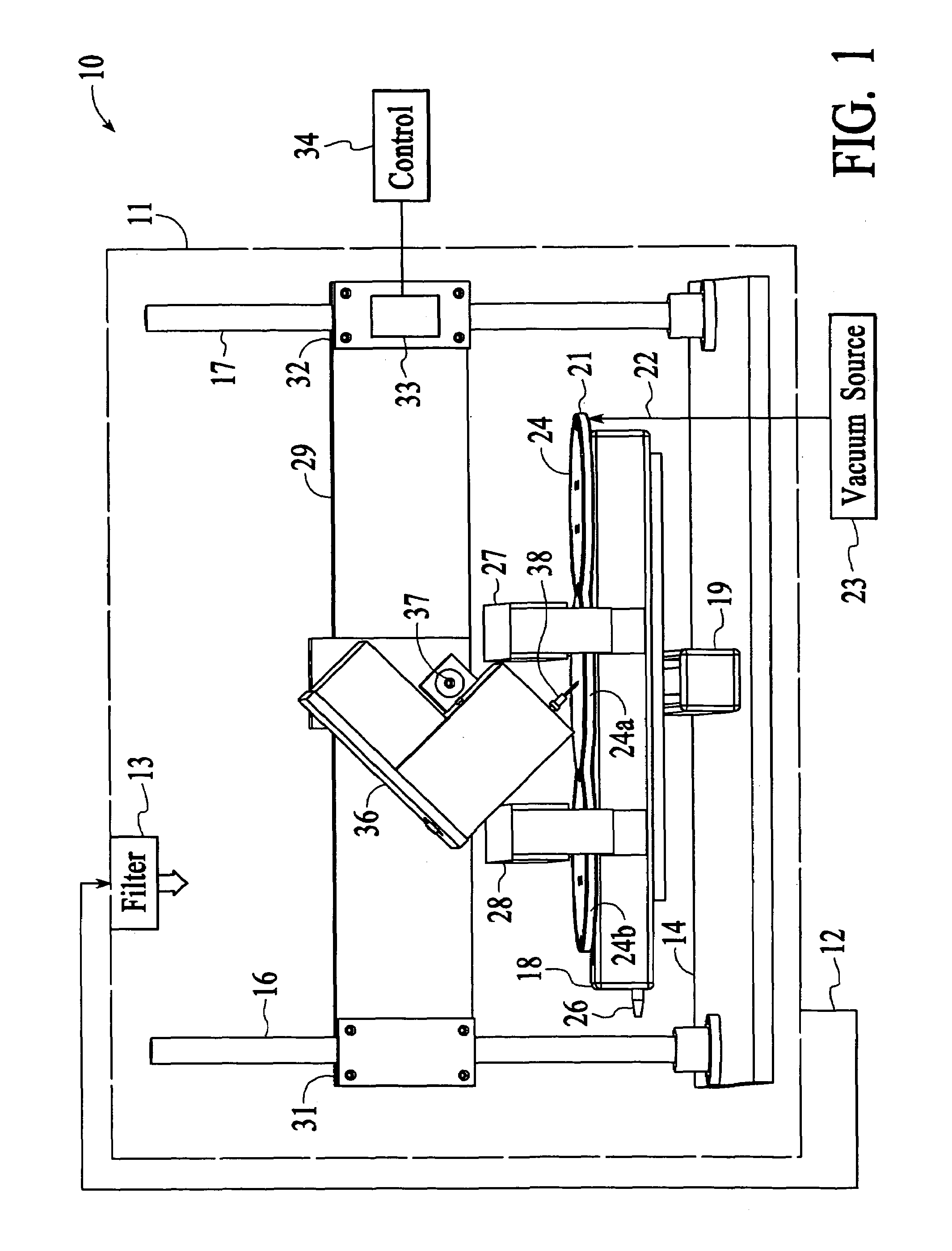
[0041]The present invention will be described in greater detail with reference to certain preferred embodiments and certain other embodiments, which may serve to further the understanding of preferred embodiments of the present invention. As described elsewhere herein, various refinements and substitutions of the various embodiments are possible based on the principles and teachings herein.

[0042]The present invention generally is related to the following U.S. patents / applications that are assigned to the assignee of the present invention: METHODS FOR CLEANING SURFACES SUBSTANTIALLY FREE OF CONTAMINANTS, application Ser. No. 09 / 636,265, filed on Aug. 10, 2000, now U.S. Pat. No. 6,530,823; APPARATUS FOR CLEANING SURFACES SUBSTANTIALLY FREE OF CONTAMINANTS, application Ser. No. 09 / 637,333, also filed on Aug. 10, 2000, now U.S. Pat. No. 6,543,462; and METHODS FOR CLEANING SURFACES SUBSTANTIALLY FREE OF CONTAMINANTS UTILIZING FILTERED CARBON DIOXIDE, application Ser. No. 10 / 359,806, now ...


PUM

PropertyMeasurementUnit
frequenciesaaaaaaaaaa
diameteraaaaaaaaaa
temperatureaaaaaaaaaa

Abstract

A method for manufacturing an article having polymeric residue that is to be removed during the manufacture of the article is disclosed. The article is introduced into a controlled environment of a processing tool having one or more processing chambers. Free radicals are generated from one or more reactant gases and introduced into at least one of the one or more processing chambers where they react with the polymeric residue. A cryogenic cleaning medium is supplied into at least one of the one or more processing chambers where the cryogenic cleaning medium removes the polymeric residue present after the free radicals react with the polymeric residue. The reactant gases are selected to facilitate removal of the polymeric residue with the cryogenic cleaning medium. The cryogenic cleaning medium is supplied with a pulsating flow via a nozzle implement that sweeps across the article. The pulsating flow may be generated via a piezo device or a rotating shaft with a hole the periodically enables or interrupts flow through a flow channel.

Description

[0001]This application is a continuation in part of application Ser. No. 10 / 894,626, filed on Jul. 19 / 2004 now U.S. Pat. No. 7,040,961 which is a continuation of application Ser. No. 10 / 208,156, filed on Jul. 29, 2002 now U.S. Pat. No. 6,764,385.FIELD OF THE INVENTION[0002]This invention relates to systems and methods for removing photoresist or other materials from an integrated circuit structure with a dry process, preferably in a vacuum stripping chamber, such as photoresist remaining after etch, implant or other fabrication steps. The invented system and method also can desirably remove etch residues remaining from previous fabrication step(s). The present invention also is suitable for cleaning surfaces on hard disks, semiconductor wafers, delicate optics, etc. The present invention more particularly relates to a preferably oscillating or / and pulsating nozzle cleaning system preferably dispensing cryogenic, solvent or solvent combination cleaning mediums, combined with plasma e...

Claims


Application Information

Patent Timeline
Patent Type & Authority Patents(United States)
IPC IPC(8): C23F1/00B08B5/02B08B7/00B24C1/00H01L21/00
CPCB08B5/02B08B7/0035H01L21/67051B24C1/003B24C5/005B08B7/0092
Inventor TANNOUS, ADEL GEORGEMAKHAMREH, KHALID
Owner NANOCLEAN TECH
Why Eureka
Try Eureka