Method of collecting chemically contaminating impurity constituents contained in air

a technology of impurity constituents and air, which is applied in the field of collecting chemically contaminating impurity constituents contained in air, can solve the problems of various quality deteriorations, unstable process conditions, and yield deterioration, and achieve high sensitivity and high accuracy

Inactive Publication Date: 2008-02-19
LAPIS SEMICON CO LTD
View PDF7 Cites 1 Cited by
  • Summary
  • Abstract
  • Description
  • Claims
  • Application Information

AI Technical Summary

Benefits of technology

[0022]The invention is intended to detect with high sensitivity and high accuracy chemically contaminating impurities in which there exist chemically contaminating impurity constituents of basic series, acidic series, and organic substance series, in gaseous and particle states, and constituents of compounds thereof, contained in air inside a clean room, as constituents having every property.

Problems solved by technology

In a manufacturing process at a semiconductor manufacturing plant and a liquid crystal manufacturing plant, besides adverse effects of fine particle contamination and metallic contamination, chemical contamination such as adsorption contamination, chemical reaction contamination, or condensation contamination of chemically contaminating impurity constituents on the surface of silicon wafers and lenses for the manufacturing equipment such as photolitho stepper, acting as factors of deterioration in reliability and yield, has given adverse effects on the surface of products (silicon wafers) processed in a manufacturing process line, thereby causing problems of various quality deteriorations.
These chemically contaminating impurity constituents in gaseous or molecular state undergo chemical reaction with each other or condensation growth due to a change in environmental conditions inside the clean room, and are transformed into fine particles or compounds in gaseous or molecular state, having different properties, to be thereby adhered to the surface of wafers during a manufacturing process as surface contaminating constituents, thus creating a cause for unstableness in process conditions or a cause for deterioration in yield.
Further, in operating conditions of manufacturing equipment in an unsteady state as well, there occurs evolution of chemically contaminating impurity constituents in a considerably larger amount than in a normal case, and the chemically contaminating impurity constituents are carried to wafers, a container for transporting the wafers, the surface of glass, and the surface of lenses inside a stepper equipment, which are exposed to the air in the cleaning room, to be adhered or adsorbed thereto due to physical and chemical reactions.
However, there is the following problem with any of the detection methods described above, such as the laser scattering method, chemical reaction adsorption-separation method, electron beam or X-ray irradiation method, and thermal programmed desorption analytical method.
Firstly, in the case of detecting fine particles by the laser scattering method, fine particles less than 0.05 μm in grain size can not be counted, and it is necessary to check the interrelation between the shape of the fine particles and the counting device.
There occurs a problem in that sufficient scattering signals can not be obtained in terms of an S / N ratio when a grain size is not more than 0.1 μm.
Further, in the case of extracting the organic substances by the adsorption-separation method, the method of extracting the organic carbons is difficult to perform, and there is a problem with the Secondary Ion Mass Spectroscopy (SIMS) analytical method in that analysis of bacteria, and so forth, and determination of the contaminated spots are not possible to implement.
In the case of detecting metal ion impurities by use of electron beam or X-ray, evaluation of concentration at a level less than 109 atoms / cm2 is unfeasible, and there is a problem with dependency on the recovered liquid species, and high sensitivity.
This method has a problem in that it is dependent on the shape and species of fine particles, and microscopic asperities on a wafer surface are detected as measured values.
Further, in the case of detecting the adsorbing molecules by the TDS analytical method, quantification and identification is difficult to achieve due to a change in adsorption and release states of water molecules, and so forth, and a change in surface property and crystalline condition of adsorption surfaces.
For example, it is not possible to perform analysis of heavy elements by the TOF-SIMS analytical method, which has a problem with high sensitivity and quantification.
That is, with any of the detection methods described in the foregoing, there is a problem in that detection is effected by reaction, decomposition, or dissociation, taking place only once, and consequently, it is not possible to separate interfering constituents simultaneously interfering with each other.

Method used


Image

  • Method of collecting chemically contaminating impurity constituents contained in air
  • Method of collecting chemically contaminating impurity constituents contained in air
  • Method of collecting chemically contaminating impurity constituents contained in air

Examples


first embodiment

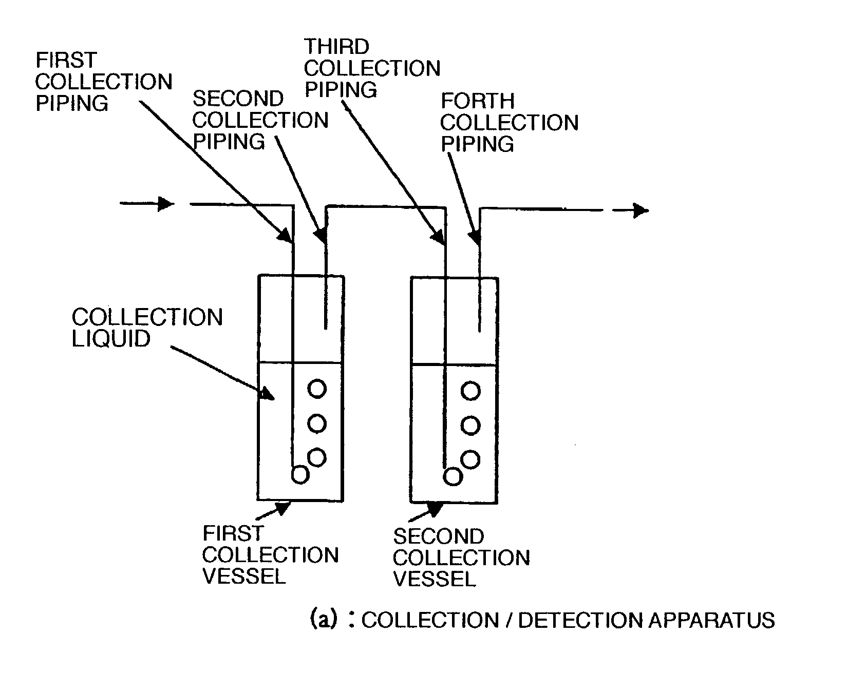
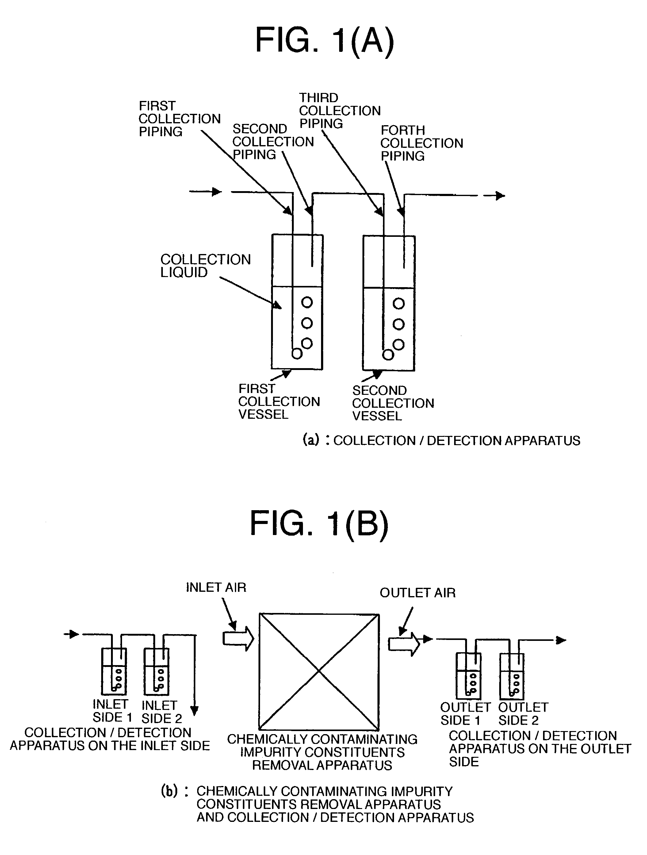
[0026]FIG. 1(a) is a schematic illustration showing a collection / detection apparatus for carrying out a first embodiment of a detection method according to the invention, for collecting chemically contaminating impurity constituents contained in circulating air inside a clean room for semiconductor manufacturing plants, incorporating the function of collecting the chemically contaminating impurity constituents contained in air. FIG. 1(b) is a schematic illustration showing an overall system wherein the collection / detection apparatus is installed on the inlet side and the outlet side of a chemically contaminating impurity constituent's removal apparatus, respectively.

[0027]As shown in FIG. 1(a), the method for collection and detection is carried out with a system configuration wherein (1) a first collection piping, (2) a first collection vessel containing a first collection liquid, (3) a second collection piping, (4) a third collection piping, (5) a second collection vessel containi...

second embodiment

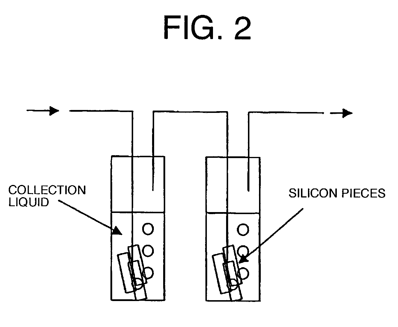
[0033]A basic system configuration of a collection and detection unit, adopted for a second embodiment of a method of collecting chemically contaminating impurity constituents in air according to the invention, is the same as that in the case of the first embodiment shown in FIG. 1. The second embodiment differs from the first embodiment in that with the second embodiment, for example, silicon pieces used as adsorbents are dipped in a solution inside a collection vessel at respective stages. As a result, detection efficiency for water-soluble organic substances can be enhanced. Further, advantageous effects of the second embodiment of the invention can be enhanced more than those for the first embodiment. Still further, as for the number of the collection vessels linked together in series, any number thereof may be used with either the first embodiment or the second embodiment.

[0034]Now, the advantageous effects of the invention are recapped as follows. As described hereinbefore, wi...


PUM

PropertyMeasurementUnit
grain sizeaaaaaaaaaa
solubilityaaaaaaaaaa

Abstract

The method is intended to detect with high sensitivity and high accuracy chemically contaminating impurities in which there exist chemically contaminating impurity constituents of basic series, acidic series, and organic substance series, in gaseous and particle states, and constituents of compounds thereof, contained in air inside a clean room, as constituents having every property. To this end, ions composed of various cations and anions, constituting the chemically contaminating impurities in fine particle, gaseous, or molecular state, are caused to continuously undergo dissolution reaction and dissociation reaction in a solution in sequence from those constituting salts having strong solubility or strong dissociative tendency.

Description

BACKGROUND OF THE INVENTION[0001]The present invention relates to a technique for detection of trace amounts (at a ppb to ppt level in concentration) of water-soluble chemically contaminating impurity constituents contained in air inside a clean room. The invention is suitably applied to a method of detecting chemically contaminating impurity constituents in a gaseous or molecular state, evolved from constituent members of a building used as a clean room of a semiconductor manufacturing plant, or manufacturing equipment installed inside the clean room, chemicals used in a manufacturing process, constituent components of auxiliary facilities such as service supply facilities, humans themselves, and so forth, including, for example, chemically contaminating impurity constituents of acidic, basic, condensate (organic substance) series, and dopant series, and constituents of compounds thereof.[0002]As for control of contamination on the surface of semiconductor silicon wafers, it has be...

Claims


Application Information

Patent Timeline
Patent Type & Authority Patents(United States)
IPC IPC(8): G01N30/00F24F7/06G01N1/22G01N1/34G01N33/00
CPCG01N1/22G01N1/34G01N33/0011Y10T436/25875Y10T436/25375Y10T436/255Y10T436/25125G01N2001/4066
Inventor WAKAMATSU, HIDETOSHI
Owner LAPIS SEMICON CO LTD
Why Eureka
Try Eureka