
Implantable medical devices with fluorinated polymer coatings, and methods of coating thereof

a technology of fluorinated polymer and medical devices, which is applied in the field of implantable medical devices with fluorinated polymer coatings, and methods of coating thereof, can solve the problems of the toxic effect of transition metal ions on the surrounding tissue, and the corrosion of the metallic surface of the stent, etc., and achieves the effect of low friction coefficien

Active Publication Date: 2009-01-13
CR BARD INC
View PDF15 Cites 23 Cited by
  • Summary
  • Abstract
  • Description
  • Claims
  • Application Information

AI Technical Summary

Benefits of technology

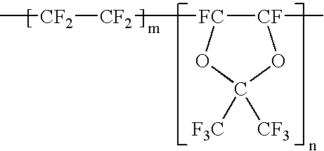
"The present invention provides a method for coating metallic medical devices with a corrosion-resistant coating of fluoropolymer. The coating is made of an amorphous fluoropolymer comprising tetrafluoroethylene and 4,5-difluoro-2,2-bis(trifluoromethyl)-1,3-dioxole. The coating can be applied to a variety of medical devices such as angioplasty balloons, catheters, guide wires, vascular patches, and drug-eluting stents. The coating can provide a thin layer of protection against corrosion and can also release therapeutic agents. The coated devices can be made opaque, radioopaque, or porous. The invention provides a method for improving the safety and efficacy of metallic medical devices."

Problems solved by technology

Another possible cause of restenosis is the recoil of the metallic surface of the stent when placed along the internal wall of the artery.
Some metallic devices such as vascular stents, made from stainless steel or Nitinol alloys (Shape Memory Alloys, such as Nickel Titanium alloy), may undergo corrosion upon long-term implantation.
The corrosion products such as transition metal ions may be toxic to the surrounding tissue.
However, when coated stents are expanded within a blood vessel, the coefficient of expansion of the coating greatly differs from that of the expanding stent such that, upon expansion, the surface of the coating tears rendering the expanded stent uncoated.
If a thicker coating is applied, such a thick coating can deter stent expansion or can render implantation into the body difficult.
Thus, challenges remain in developing biostable metallic implantable devices.

Method used


Image

  • Implantable medical devices with fluorinated polymer coatings, and methods of coating thereof

Examples


example 1

Coating a Vascular Stent with Amorphous PTFE Polymer

[0036]In a 250 ml glass beaker, 1 g TEFLON® AF 1600 and 19 g FLUORINERT® FC40 are mixed until a homogeneous clear solution is obtained. The solution is filtered using a 0.2 micron glass filter, and then used in coating application. A Nitinol stent from Angiomed (Memoflexx stent 8 mm diameter, 50 mm length) is dipped in the polymer solution and removed from the solution. The solvent is removed by air-drying. A transparent thin polymer coating is visible on the stent surface when viewed microscope.

example 2

Method of Obtaining a Porous Fluoropolymer Coating

[0037]In a 250 ml glass beaker, 1 g TEFLON® AF 1600 and 19 g FLUORINERT® FC40 are mixed until a homogeneous clear solution is obtained. To this solution 5 g sodium chloride is added and the solution / suspension is stirred using a magnetic stirrer. A Nitinol stent from Angiomed (Memoflexx stent 8 mm diameter, 50 mm length) is dipped in the polymer solution. The solvent is removed by air-drying. The stent is then transferred into a beaker containing 1000 ml distilled water, and incubated until salt is leached out completely. The removal of salt creates a porous polymeric coating. The porosity may help to induce tissue in-growth.


PUM

PropertyMeasurementUnit
thicknessaaaaaaaaaa
thicknessaaaaaaaaaa
thicknessaaaaaaaaaa

Abstract

The present invention generally relates to implantable medical devices having a fluorinated coating, and methods of coating the same. More particularly, the present invention provides implantable metallic medical devices coated with a corrosion resistant coating comprising an amorphous fluoropolymer.

Description

CROSS-REFERENCE TO RELATED APPLICATION[0001]This application claims the benefit of priority of U.S. Provisional Application No. 60 / 549,770, filed Mar. 3, 2004, and of U.S. Provisional Application No. 60 / 529,402, filed Dec. 12, 2003.BACKGROUND OF THE INVENTION[0002]Implantable stents and other expandable medical devices have been increasingly used in many minimally invasive surgical procedures such as balloon angioplasty. Stents mitigate complications of acute and subacute vessel closure, intimal dissection, and elastic recoil of the vessel wall, and reduce angioplasty-related restenosis rates. Restenosis can be caused by incompatibility of the metallic surface of the stent that engages the inner walls of the blood vessel, giving rise to subacute thrombosis. Another possible cause of restenosis is the recoil of the metallic surface of the stent when placed along the internal wall of the artery. In-stent restenosis usually occurs within weeks to months of stent implantation.[0003]Some...

Claims


Application Information

Patent Timeline
Patent Type & Authority Patents(United States)
IPC IPC(8): A61F2/06A61L31/10A61L31/16B05D1/02B05D1/18
CPCA61L31/10C08L27/18
Inventor PATHAK, CHANDRASHEKHAR PRABHAKAR
Owner CR BARD INC
Learn More