Stent for blood vessel and material for stent for blood vessel

a technology for stents and blood vessels, applied in the field ofluminal stents, can solve the problems of re-stenosis caused by excessive hyperplasia, affecting the effect of stent implantation,

Inactive Publication Date: 2009-03-03
KYOTO MEDICAL PLANNING
View PDF6 Cites 48 Cited by
  • Summary
  • Abstract
  • Description
  • Claims
  • Application Information

AI Technical Summary

Benefits of technology

[0012]It is therefore an object of the present invention to provide a luminal stent, in which a stent formed of a biodegradable polymer material is used as an LDDS member, a drug with sufficient pharmaceutical effect is impregnated in the stent formed of a biodegradable polymer material, without losing the pharmaceutical effect, the stent can be implanted and left at a local area at the target site in the blood vessel, without the drug becoming peeled off from the stent surface, and in which the drug of the effective concentration can be released for a required duration. It is another object of the present invention to provide a manufacturing method for the luminal stent.
[0017]The present invention also provides a luminal stent in which a layer of a biodegradable polymer material is further provided on the surface of a stent formed of a biodegradable polymer material, which is swollen and impregnated with a drug, such as to control the release rate of the drug impregnated into the biodegradable polymer layer forming the stent.
[0024]With the luminal stent, according to the present invention, a sufficient quantity of the drug is impregnated with no loss of its pharmaceutical effect or no risk of peeling, thereby enabling a required quantity of the drug to be released continuously for a required duration to the wall of the blood vessel an into the blood flow.
[0025]With the luminal stent, according to the present invention, the drug impregnated into the inside of the stent is released with progress in the degradation of the biodegradable polymer material, forming the stent, thus enabling the drug to be released positively to the target site in the blood vessel carrying the stent.
[0026]By forming a further biodegradable polymer layer on the stent surface, it becomes possible to control the release rate of the drug into the blood, impregnated in the inside of the stent.

Problems solved by technology

In angioplasty, mechanical techniques such as balloon expansion or stent implantation is likely to damage the blood vessel.
On the other hand, re-stenosis is caused by excessive hyperplasia of cells.
However, deleterious side effects have been pointed out because systemic medication at a high concentration or in a large quantity is required in order to achieve the effect of these drugs.
With these methods, it is necessary to keep the catheter inserted continuously over a prolonged time in the blood vessel, therefore the blood flow is interrupted, so that sufficient effect of the drug is difficult to achieve and consequently none of the methods has been put to practical use.
With metal, it is only possible to deposit a drug on its surface, while it is not possible to impregnate the metal itself with the drug.
In case the drug is deposited on the metal stent by coating or bonding, there is presented a problem that the drug itself becomes peeled off from the stent surface.
It is also difficult to have a quantity of the drug sufficient to manifest its pharmaceutical effect deposited on the stent surface.
With the method of covering the stent with a polymer sheet, the polymer sheet impregnated with a drug needs to be prepared at a high temperature, thus possibly detracting from the pharmaceutical effect of the drug.

Method used


Image

  • Stent for blood vessel and material for stent for blood vessel
  • Stent for blood vessel and material for stent for blood vessel
  • Stent for blood vessel and material for stent for blood vessel

Examples


experimental example 1

[0077]In the present experimental example, a plural number of fibers, each impregnated with a drug, were prepared, as the pressure and the temperature of CO2 were changed, and the tensile strength was measured of each PLLA fiber.

example 1

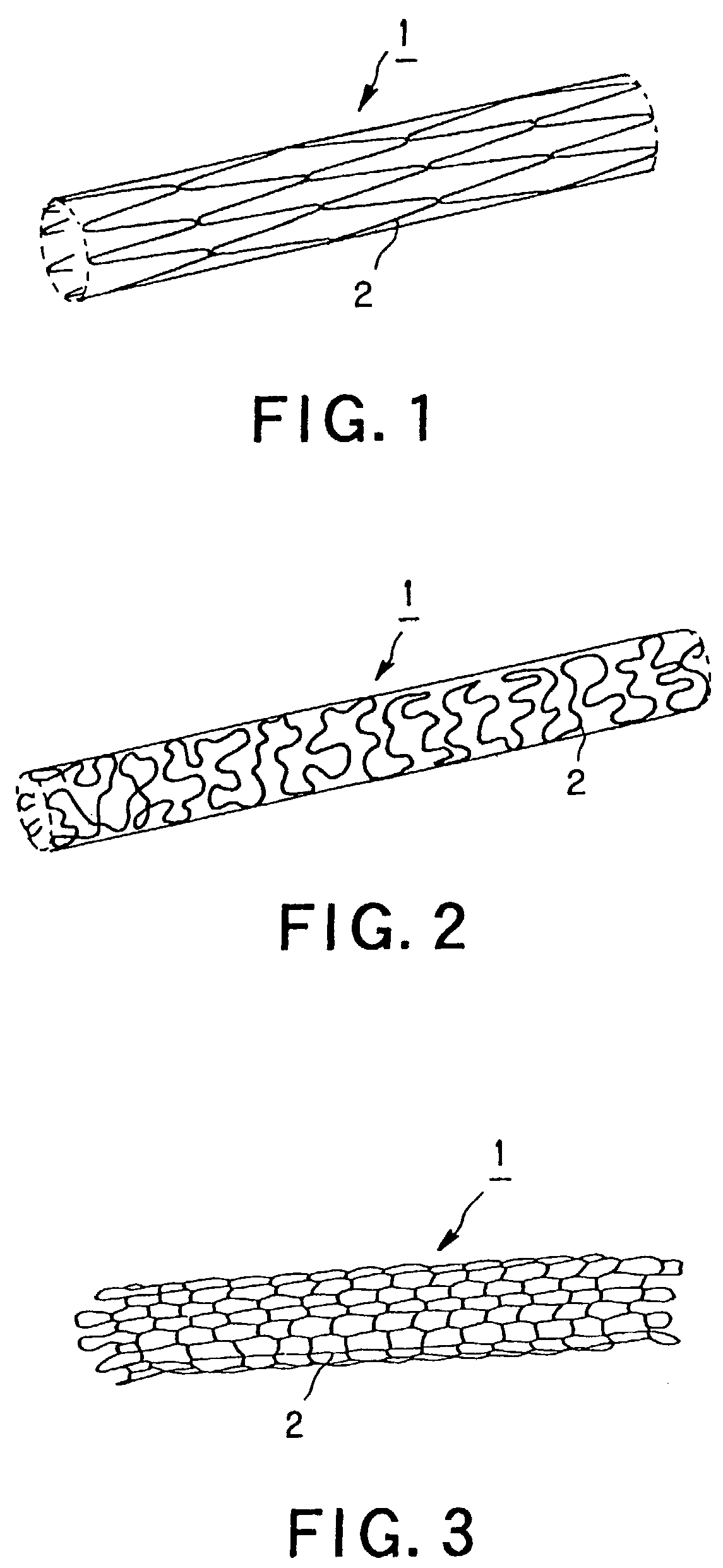
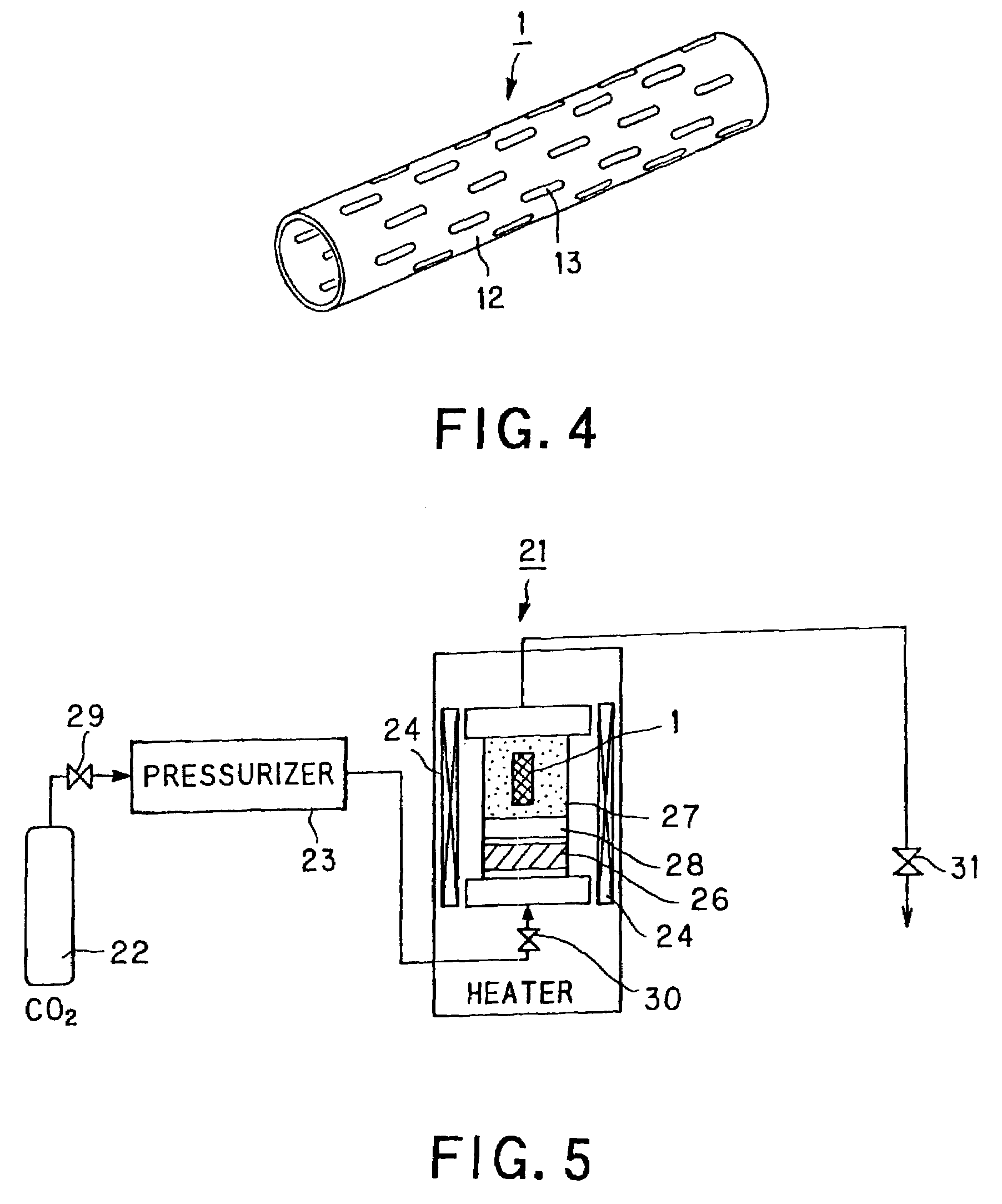
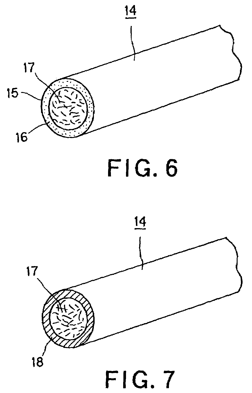
[0078]First, a PLLA fiber 170μm in diameter and tranilast [N-(3,4-dimethoxy cinnamoyl) anthranilic acid], exhibiting intimal hyperplesia suppressing effect, were charged into a pressurized vessel 27 of the device 21 shown in FIG. 5. At this time, a porous filter was inserted into the space between the PLLA monofilament and tranilast. Meanwhile, tranilast is a drug effective in suppressing re-stenosis which occurs after the angioplasty.

[0079]Then, CO2 was pressurized to 10 MPa by a pressurizer 23 and a second valve 30 was opened to inject it into the pressurized vessel 27. CO2 pressurized in the pressurized vessel 27 was warmed to 80° C. to set it to a state of supercritical state fluid.

[0080]After the PLLA fiber and tranilast were exposed to CO2 in the state of the supercritical fluid for two hours, CO2 was gradually exhausted to set a state opened to atmosphere. This yields a tranilast-impregnated PLLA fiber.

experimental example 2

[0091]In the experimental example 2, a plural number of luminal stents, formed of plural biodegradable polymer material, in particular plural fibers of biodegradable polymer, in which the drug was impregnated as the pressure and the temperature of CO2 were varied, were formed, and measurements were made of the amount of the drug for each of these stents.


PUM

PropertyMeasurementUnit
pressureaaaaaaaaaa
tensile strengthaaaaaaaaaa
pressureaaaaaaaaaa

Abstract

A luminal stent, implanted and implanted and left in the blood vessel, is disclosed. By permitting a stent (1), formed of a biodegradable polymer material (2), to be swollen, and by impregnating the swollen stent (1) with a drug, a sufficient quantity of the drug is impregnated in the stent. This drug is continuously released into the blood vessel over a prolonged time. A biodegradable polymer layer is formed on the surface of the stent (1) impregnated with the drug, and the release rate of the drug impregnated in the stent is controlled.

Description

TECHNICAL FIELD[0001]This invention relates to a luminal stent, introduced in the blood vessel. More particularly, it relates to a luminal stent in which a drug is impregnated into the material forming the stent.BACKGROUND ART[0002]In angioplasty, mechanical techniques such as balloon expansion or stent implantation is likely to damage the blood vessel. In a site of lesion of the blood vessel, acute closure, caused by thrombosis, or re-stenosis caused by intimal hyperplasia of the blood vessel, as a curative reaction of the blood vessel wall, occurs frequently.[0003]The acute closure is correlated with thrombosis. For its prevention, an anti-thrombotic therapy is performed by systemic medication, usually through a vein.[0004]On the other hand, re-stenosis is caused by excessive hyperplasia of cells. At present, researches into drugs suppressing this hyperplasia of cells are advancing rapidly, and several drugs have demonstrated satisfactory results.[0005]However, deleterious side ef...

Claims


Application Information

Patent Timeline
Patent Type & Authority Patents(United States)
IPC IPC(8): A61F2/00A61F2/06A61L33/00B05D3/00A61F2/02A61F2/82A61L31/10A61L31/16A61M29/02
CPCA61F2/90A61L31/10A61L31/16C08L67/04A61F2210/0004A61F2250/0067A61L2300/416A61L2300/42A61L2300/604
Inventor IGAKI, KEIJIYAMANE, HIDEKI
Owner KYOTO MEDICAL PLANNING
Why Eureka
Try Eureka