Combustion installation with CO2 recovery

a technology of co2 recovery and combustion installation, which is applied in the direction of fluidised bed combustion apparatus, combustion type, lighting and heating apparatus, etc., can solve the problems of gaseous cosub>2, thermal regeneration, and penalize the energy efficiency of the electricity and/or steam production installation, so as to reduce the cost of co2 capture

Active Publication Date: 2009-05-19
GENERAL ELECTRIC TECH GMBH
View PDF4 Cites 26 Cited by
  • Summary
  • Abstract
  • Description
  • Claims
  • Application Information

AI Technical Summary

Benefits of technology

[0010]The invention provides a combustion installation for burning carbon-containing solid materials that operates at atmospheric pressure, with integrated CO2 capture, and requires no separation of air beforehand and no recycling of CO2 to substitute for nitrogen in the combustion air. By virtue of its simplicity and its compactness, this system reduces CO2 capture costs and produces steam for generating electricity.

Problems solved by technology

Burning fossil fuels results in emission of gaseous CO2 and of SO2 in small quantities.
Furthermore, thermal regeneration has the drawback of necessitating large quantities of steam, which penalizes the energy efficiency of the electricity and / or steam production installation.
However, the oxygen has to be produced from air by an air separation unit and a cryogenic system that consumes a great deal of energy.
The gasification reaction uses oxygen under pressure produced by an air separator unit, which is costly.
Apart from its complexity, the above type of installation is somewhat unreliable, as its availability is typically only 80%.
However, to use gaseous fuel, which is very costly, it may be more economical to use high-efficiency (60%) gas turbines associated with heat recovery installations for treating the flue gases, rather than boilers coupled to a lower efficiency (45%) steam turbine.
Unfortunately, all these post-combustion CO2 capture techniques have the drawback of increasing by a factor of up to two the investment cost of a conventional coal power station and require a large footprint.

Method used


Image

  • Combustion installation with CO2 recovery
  • Combustion installation with CO2 recovery
  • Combustion installation with CO2 recovery

Examples


Embodiment Construction

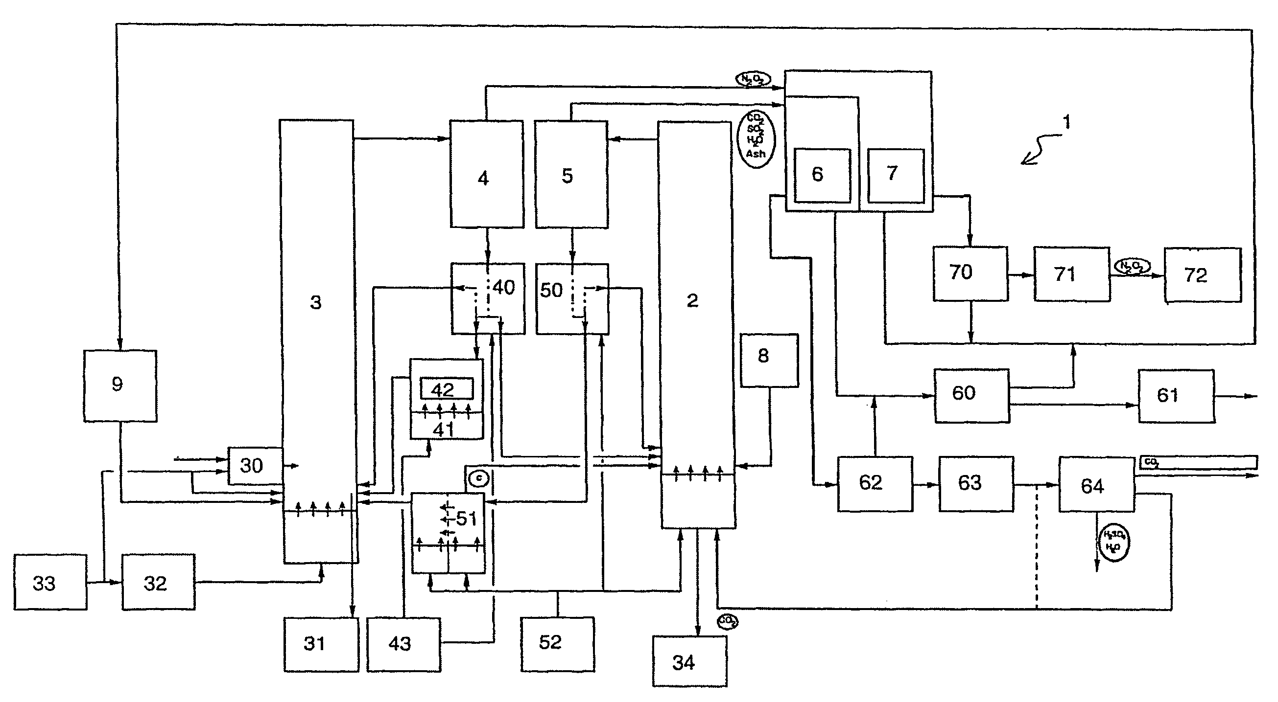
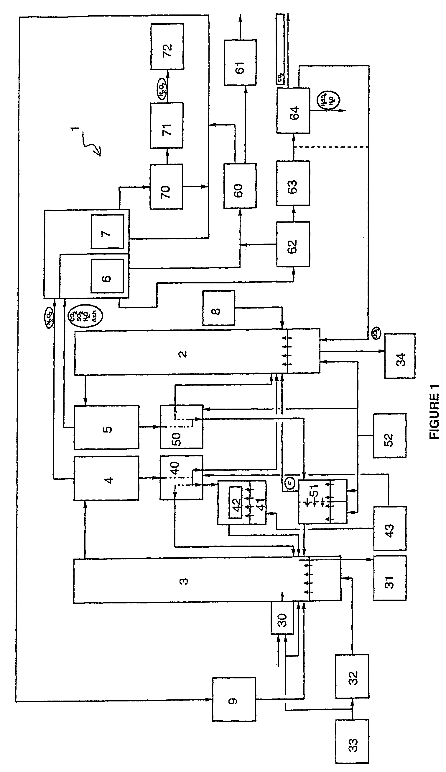
[0027]The installation 1 includes an oxide reduction reactor 2, an oxide oxidation reactor 3, two cyclones 4 and 5, each dedicated to one reactor, and two rear cages 6 and 7 containing recovery exchangers 66 for the flue gases and 73 for the air, each dedicated to one of the reactors.

[0028]The reduction reactor 2 is fed with fuel from a pulverized coal silo 8. The coal is coarsely ground beforehand.

[0029]The reactor 2 is fluidized by a mixture of steam and recycled CO2. When the installation is started up, the bed is fluidized only by steam.

[0030]After reduction in the reactor 2, the oxides enter the cyclone 5 in which the solid oxide particles are separated from the fly ash and the combustion gases, consisting of CO2, SO2 and steam.

[0031]The fly ash and the combustion gases then enter the heat exchangers 6. The fly ash is separated from the combustion gases in a bag filter 62. The mixture of CO2, H2O and SO2 is then fed into the cooling and condensing circuit 64 via an induced draf...


PUM

PropertyMeasurementUnit
pressureaaaaaaaaaa
temperatureaaaaaaaaaa
densityaaaaaaaaaa

Abstract

An installation for combustion (1) of carbon-containing solids includes an oxide reducing reactor (2), a first cyclone (5), a recuperator (6), an oxidation reactor (3), a second cyclone (4), wherein flows an oxide which is reduced then oxidized in each of the two reactors (2 and 3). In the installation, the fuel is ground before being introduced into the reduction reactor (3). The reduced size of the solid fuel particles enables more complete and faster combustion and enables almost 100% production of fly ashes which are separated from the circulating oxides.

Description

RELATED APPLICATIONS[0001]The present application is a national phase application of PCT / FR2004 / 050000, which in turn claims the benefit of priority from French Patent Application No. 03 00432, filed on Jan. 16, 2003, the entirety of which are incorporated herein by reference.FIELD OF THE INVENTION[0002]The present invention relates to combustion installations for burning carbon-containing solid materials to produce electricity and / or steam. The solid materials can be fossil fuels such as coal, for example, waste or biomass, and they are injected into a combustion chamber, for example a fluidized bed combustion chamber.BACKGROUND OF THE INVENTION[0003]Burning fossil fuels results in emission of gaseous CO2 and of SO2 in small quantities. The injection of limestone into the combustion chamber reduces the emission of SO2 in situ, but this reduction in the emission of SO2 is accompanied by production of secondary CO2 in addition to the CO2 produced by combustion of the carbon-containin...

Claims


Application Information

Patent Timeline
Patent Type & Authority Patents(United States)
IPC IPC(8): F23B30/00F23C10/00F23C99/00F23G5/30
CPCF23C10/002F23C10/005F23C99/00F23G5/30F23C2900/99008Y02E20/346Y02E20/34
Inventor MORIN, JEAN-XAVIERBEAL, CORINNE
Owner GENERAL ELECTRIC TECH GMBH
Why Eureka
Try Eureka