[0034]The pad conditioning
system used in the present invention, as set forth in U.S. Pat. No. 6,508,697 referred to above, utilizes
abrasive disks that have an
open structure to collect debris or
swarf as it is being abraded off of the
substrate surface. The
system has a pad conditioning apparatus, process fluids, a vacuum capability to pull
waste material out of the conditioning pad, self-contained flushing means, and a piezo-electric device for vibrating the pad conditioning
abrasive. The debris, as it is being created, is pulled through the holes of the
abrasive and magnetic support, into a chamber behind the support, and into a conduit to a disposal system. Jets of water, other cleaning or neutralizing chemicals are sprayed through the abrasive in conjunction with the waste removal. This flushing / abrading / vacuum cleaning thoroughly cleans the polishing pad surface, enabling alternative materials to be introduced without cross
contamination. All of these elements combine in operation to provide a unique and effective system for conditioning and cleaning polishing pads. They also allow for the introduction into the conditioning, cleaning and polishing processes operation-specific slurries or other chemicals, without the need for extensive retooling, platen change-out, and / or additional
material handling.
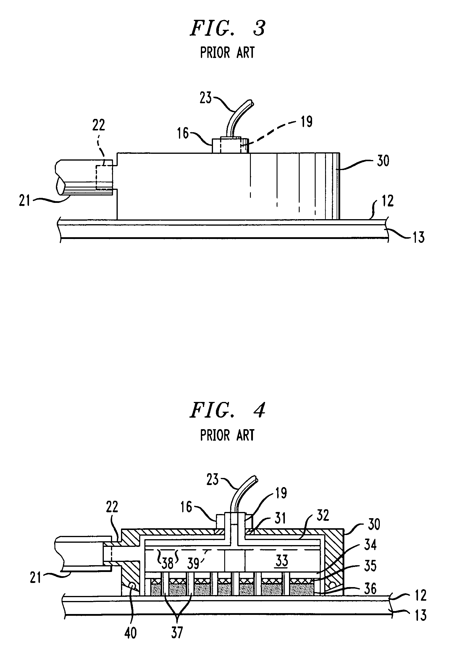
[0037]A series of pressurized water holes radiating out from the center of the
impeller disk allows
full coverage of the abrasive disk and aids in the break up of the static
layers in the pores of the polishing pad. The vacuum action pulls the water and debris immediately up through the aligned holes in the support, magnetic, and abrasive disks, and the rotating
impeller blades sweep the water and debris into the vacuum
pickup outlet and into the disposal system. The aligned holes, or “
open structure”, in the stacked disks allows collection of debris or
swarf, as it is being dislodged from the surface of the pad, allowing continuous conditioning and cleaning without interference of the debris between the abrasive disk and the surface of the
wafer. The magnetic fastening structure allows for rapid
changeover and provides controlled flatness for the abrasive. A mechanical method can also be used which would be gimbaled for alignment and
cushioning. One exemplary mechanical method of providing this gimbaling comprises a ball and socket design that functions to level the abrasive disk within the conditioning holder. Barbed fittings may be used with the ball and socket arrangement to provide a means for
coupling a pressurized medium into the conditioning holder. The use of a gimbaled arrangement allows for the independent control of the various force elements (e.g.
downforce, vacuum) involved in the conditioning process (which may further include the force of an incoming
stream of conditioning fluids onto the pad surface at a pressure of, for example, 100 psi). The independent control of the movement / applied force of the conditioning holder / apertured disk with respect to the outer chamber allows for the arrangement to respond to sheer (normal) force without the use of a relatively high conformal force. Therefore, as stated above, the
elimination of any dependence between the two forces allows for a “zero”
downforce to be imparted (that is, a lifting of the conditioning holder) while allowing the outer chamber (and associated vacuum) to remain in contact with the pad surface. Vacuum pulls the wastes from the process, and lifts the polishing pad asperities into an uncompressed position. Select holes also introduce process fluids, such as cleaning chemicals,
slurry, passivating agents, complexing agents, surfactants, and UPW, and even cleaning gasses, to the pad in a much more controlled (pressure, location, sequence, and pad / wafer
surface conditions, for instance) fashion.
[0038]A self-contained flushing system provides water to loosen and flush the debris up the disks holes into the
impeller chamber and on through to the disposal system. A sealed bearing at the top of the outer chamber prevents water or process fluids from escaping. This flushing method also reduces the amount of UPW that is presently needed to flush the polishing pad. This saves on costly
slurry, the volume of UPW, and the expensive
waste disposal.
[0039]The impeller provides firm backing for the magnetic disk or mechanical fastening and abrasive disk. The
magnet is secured to the support disk mechanically or by an
adhesive. The abrasive disk is either magnetically or mechanically secured to the support disk. This system allows for periodic cleaning of the pad conditioning apparatus, as well as periodic replacement of the
magnet and abrasive disks, without the need to disassemble the entire outer chamber and inner impeller
assembly, which would incur extensive down time.
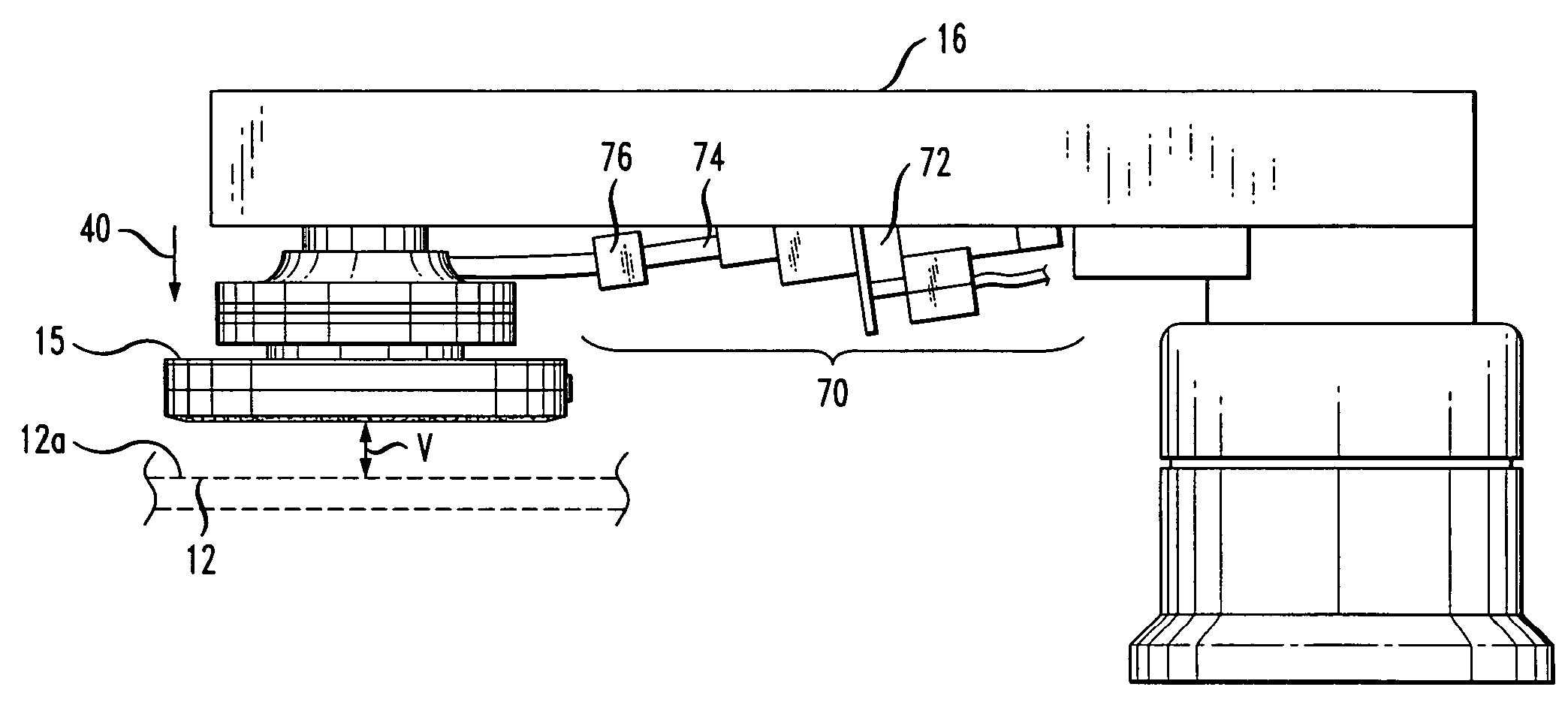
[0040]A piezoelectric
transducer is provided near the free end of the end
effector arm or fluid
stream. When excited with a
high frequency voltage,
transducer imparts a low amplitude vibration to the pad conditioning apparatus, further enhancing the
breakup and removal of the static layer of
slurry on the polishing pad surface. A small
vertical force imparted by the end effector arm on the polishing pad also aids in breaking up
glazing of the slurry, and aids in dislodging particles wedged in the polishing pad surface.

