Fuel cell with metal alloy contacts that form passivating conductive oxide surfaces

a technology of conductive oxide and metal alloy contacts, which is applied in the direction of cell components, final product manufacturing, sustainable manufacturing/processing, etc., can solve the problems of inability to measure resistance greater than about 0.0015 ohmcmsup>2/sup>(cmsup>2/sup>) and well-known electrical continuity problems. to achieve the effect of reducing the manufacturing cost of the apparatus

Inactive Publication Date: 2009-08-18
APTIV TECH LTD
View PDF30 Cites 11 Cited by
  • Summary
  • Abstract
  • Description
  • Claims
  • Application Information

AI Technical Summary

Problems solved by technology

In devices having contact surfaces for conducting electricity between two elements equipped with such contact surfaces (referred to herein as “electrical contacts”), an electrical continuity problem is well known in the art.
The non-conductive oxide surface layers increase the resistance of the metallic interface and inversely decrease the conductivity.
Practical conduction of a surface in any application depends, of course, on the applied voltage and amperage; but for many applications, for example, in fuel cell assemblies, a measured resistance of greater than about 0.0015 ohmcm2 (Ωcm2) is unacceptable.
In the prior art, electrical contacts requiring high conductivity and long durability are known to be coated with noble metals such as gold and platinum to prevent corrosion of the electrical contact surfaces, but such coatings are so expensive as to be impractical for many ordinary applications.
Graphite, however, is brittle and has relatively low strength, making it difficult to handle.
In addition, it is bulky, is expensive to machine, and is relatively porous.
However, the PEM fuel cell environment is very corrosive for all prior art materials but the noble metals, as water vapor, oxygen, and heat coexist in a PEM fuel cell.
Furthermore, during long-term operation of a PEM fuel cell, small amounts of HF and H2SO4 are known to leach out of other components, leading to either pitting corrosion or formation of a high-resistance passivating layer on the cathode side of a metal bipolar plate.
In the prior art, only conductive polymer or noble metal coatings are satisfactory solutions to this problem for metal bipolar plates, and each is expensive and requires an additional manufacturing step, which increases the overall cost of a PEM fuel cell.
Unfortunately, this initial value may change over time, because the metallic surfaces can oxidize, causing the measured resistance across the metallic interface to increase.
Hardened gold provides the most reliable and stable interconnection, but even this material will degrade to a failure level due either to diffusion of an additive (cobalt or nickel) that hardens the gold to the surface or to wear-through of the gold layer and exposure of the more reactive base metal, typically a copper alloy.
In all cases, the electrical interconnection will eventually fail.

Method used


Image

  • Fuel cell with metal alloy contacts that form passivating conductive oxide surfaces
  • Fuel cell with metal alloy contacts that form passivating conductive oxide surfaces
  • Fuel cell with metal alloy contacts that form passivating conductive oxide surfaces

Examples


Embodiment Construction

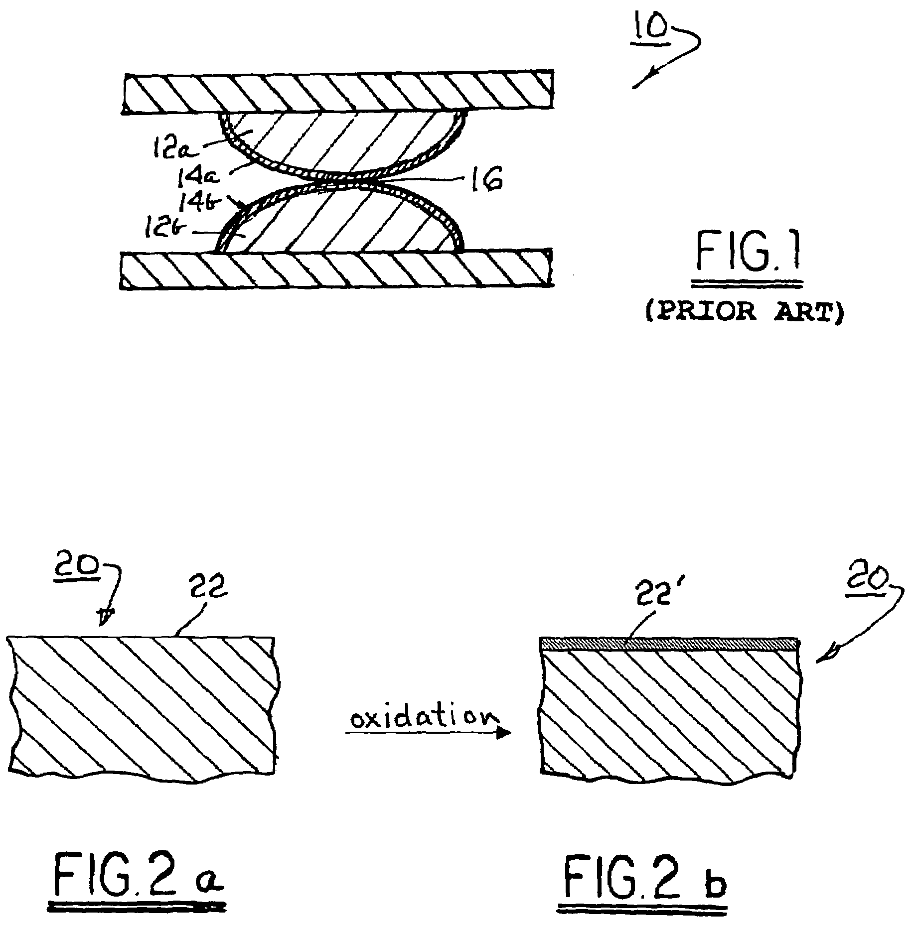
[0020]Referring to FIG. 1, a prior art electromechanical apparatus 10 includes a first electrical contact element 12a and a second electrical contact element 12b, shown in mechanical and electrical contact along respective surfaces to form an electrical interface 16. Elements 12a, 12b are brought into and out of mechanical contact by known means (not shown) to make or break electrical connection therebetween. The prior art materials of which contact elements 12a and 12b typically are formed are known to be susceptible to oxidation to form surface oxide layers 14a, 14b that are non-conductive.

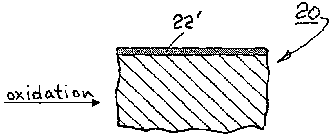
[0021]Referring to FIGS. 2a and 2b, a blank 20 comprising an alloy in accordance with the invention has a free surface 22 available for oxidation to form a surface oxide layer 22′ having a conductance of, preferably, less than about 0.0015 Ωcm2. When such alloys are substituted into apparatus 10 for forming elements 12a, 12b, the resulting surface oxide layers 14a, 14b are conductive. In electri...


PUM

PropertyMeasurementUnit
resistanceaaaaaaaaaa
conductiveaaaaaaaaaa
electrical surface resistanceaaaaaaaaaa

Abstract

A metal alloy which when oxidized forms a highly conductive surface oxide layer. Alloy compositions such as, but not limited to, Ti—Nb, Ti—Ta, La—Sr—Cr, and La—Sr—Co are known to form oxide passivation layers which are highly conductive. Such alloys are useful in electrical contact apparatus. An electrical contact element formed of the alloy has a contact surface which when oxidized forms a highly conductive surface layer, thus maintaining electrical conductivity and continuity through the element. The oxide layer may be formed in situ after assembly of the electrical contact or may be provided in an oxidative step during manufacture. The electrical contact may be formed entirely of one or more of such alloys; or may be formed of an inexpensive substrate base metal, such as steel, having one or more of the alloys coated thereupon; or may be formed of a mixture of the base metal and the alloy.

Description

RELATIONSHIP TO OTHER APPLICATIONS AND PATENTS[0001]The present application is a continuation of U.S. patent application Ser. No. 10 / 674,245, filed Sep. 29, 2003 now abandoned, which is a continuation-in-part of U.S. patent application Ser. No. 10 / 224,871, filed Aug. 21, 2002 now U.S. Pat. No. 7,037,617.TECHNICAL FIELD[0002]The present invention relates to conductive materials; more particularly, to such materials useful in forming high-conductivity, durable electrical contacts; and most particularly, to such materials which are not noble metals and which form passivating yet conductive surface oxides.BACKGROUND OF THE INVENTION[0003]In devices having contact surfaces for conducting electricity between two elements equipped with such contact surfaces (referred to herein as “electrical contacts”), an electrical continuity problem is well known in the art. As used herein, “electrical contact” should be taken to mean any surface which electrical current enters or exits, or apparatus ha...

Claims


Application Information

Patent Timeline
Patent Type & Authority Patents(United States)
IPC IPC(8): H01M8/10B05D5/12C22C9/00C23C8/10H01M8/00H01M8/02H01M8/12
CPCH01M8/0204H01M8/0228H01M8/0208Y02E60/50H01M2008/1095H01M2008/1293Y02P70/50
Inventor MANTESE, JOSEPH V.EDDY, DAVID S.AUKLAND, NEIL R.THOMPSON, MARGARITA P.WANG, SU-CHEE S.
Owner APTIV TECH LTD
Why Eureka
Try Eureka