Optical CDMA communications system using OTDL device

a communication system and optical codedma technology, applied in the field of optical codedivision multiple access communication systems, can solve the problems of inefficient dedicated bandwidth allocation architecture, low usable sequences, and users, and achieve low data rate signals, efficient utilization, and high resolution spectral separation

Inactive Publication Date: 2010-07-13
NORTHROP GRUMMAN SYST CORP
View PDF15 Cites 5 Cited by
  • Summary
  • Abstract
  • Description
  • Claims
  • Application Information

AI Technical Summary

Benefits of technology

[0017]The enabling characteristic of the OTDL is the capability to present a very long optical path within a small space and to permit a controlled tapping off of energy from the optical beam at uniform intervals. This capability is applied principally to achieve high resolution spectral separation. According to an embodiment of the present application, the capability enables a single short optical pulse to be passively converted into a large number of identical spatially distinct pulses at uniform time delays. Thus, each pulse replica may be independently modulated (coded) using simple spatial means, rather than using more complicated temporal means, prior to recombining into a time sequence of coded pulses. The long total time delay capability also means that rather low data rate signals, as low as 50 MHz, can be efficiently utilized.
[0018]The simple spatial modulation capability of the OCDMA application of OTDL enables the device of this embodiment to be low power since the OTDL is inherently a passive device and no active component needs to operate at the chip-rate. Further, the device of this embodiment i

Problems solved by technology

But in practice, due to the need to maintain low cross-correlation properties between the high rate sequences, the number of usable sequences, hence users, is somewhat less than the processing gain.
The main problem with fiber optic systems is the inefficient nature of dedicated bandwidth allocation architectures.
Many communications, particularly Internet Protocol communications, are extremely bursty.
This may not be feasible.
This inherently reduces optical efficiency because a “0” code removes or discards available light.
However, detection of bi-polar codes requires detection in the presence of an unmodulated reference beam, i.e., coherent detection.
Coherent detection is difficult and expensive to achieve in a practical system.
The Dutt system is not very optically effi

Method used


Image

  • Optical CDMA communications system using OTDL device
  • Optical CDMA communications system using OTDL device
  • Optical CDMA communications system using OTDL device

Examples


Embodiment Construction

[0040]The following detailed description is of the best presently contemplated mode of carrying out the invention. This description is not to be taken in a limiting sense, but is made merely for the purpose of illustrating the general principles of the invention. The scope of the invention is best defined by the appended claims.

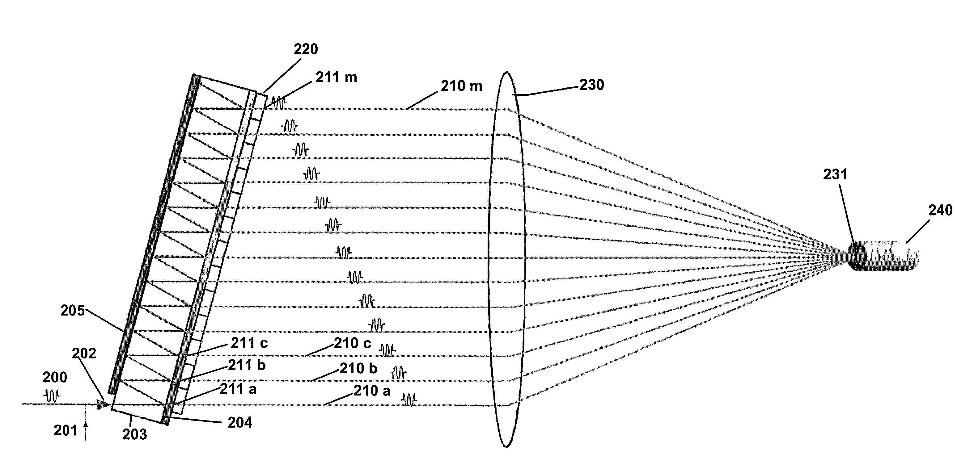
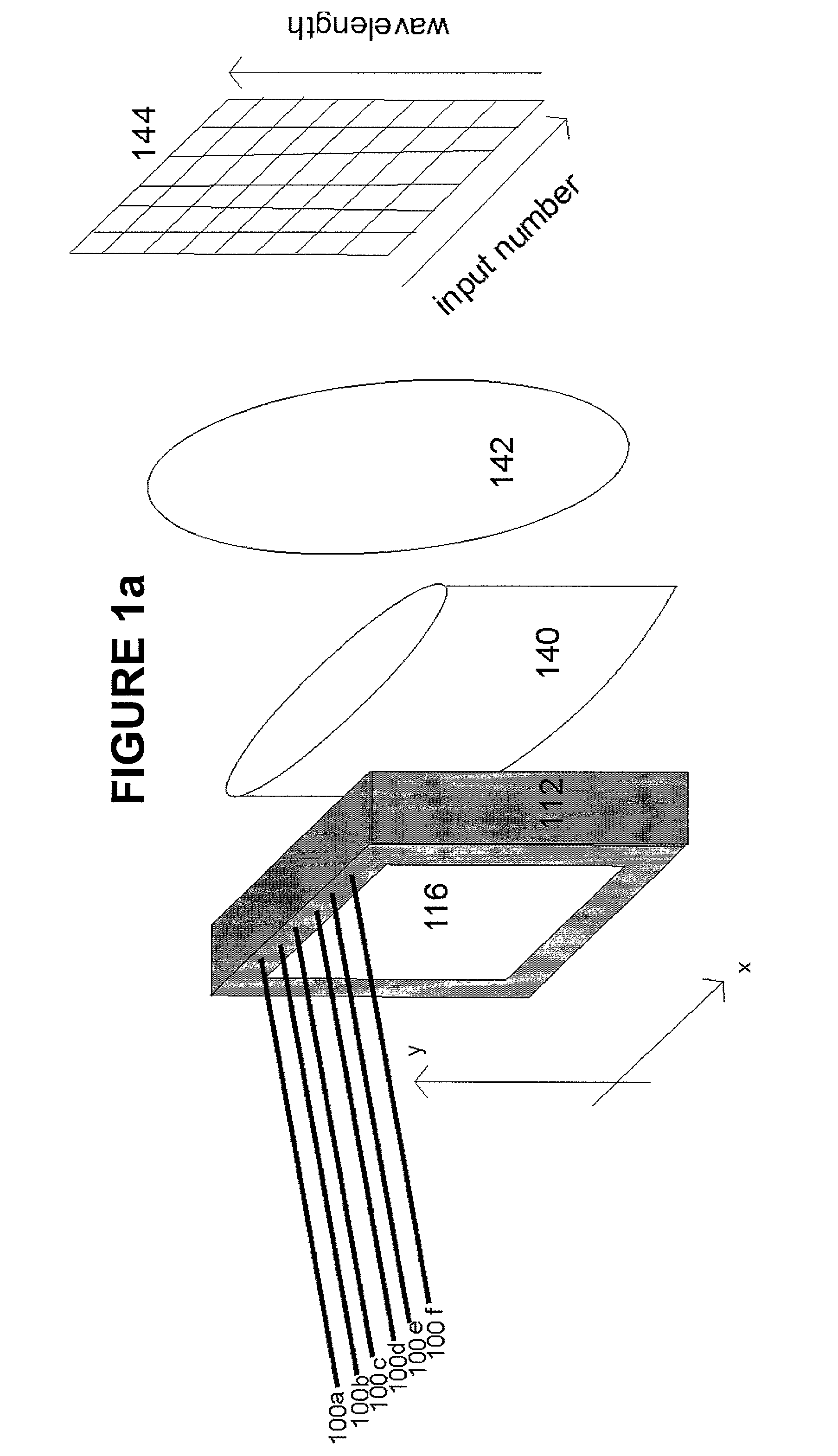
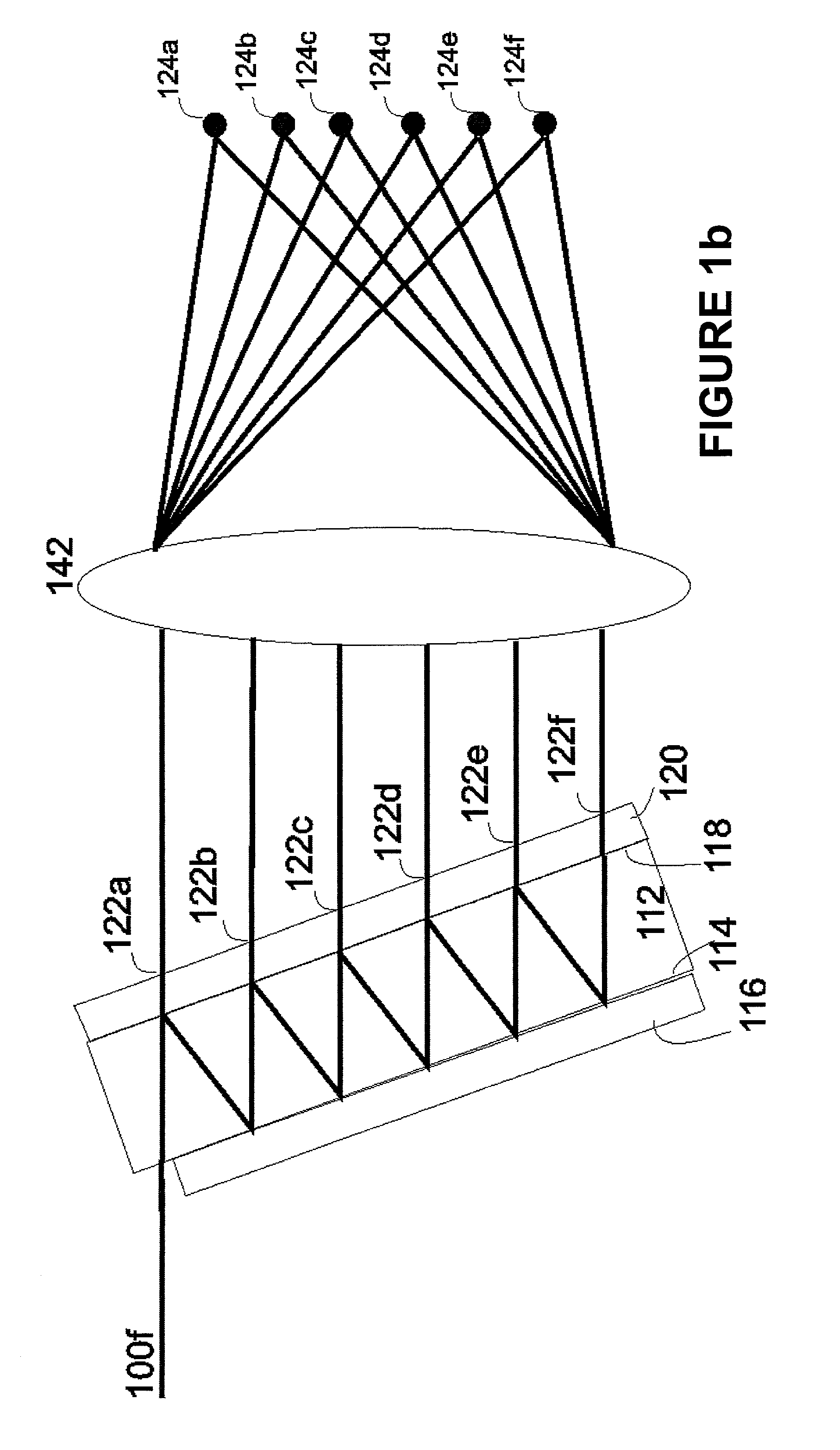
[0041]FIGS. 1(a) and 1(b) illustrate an example of an OTDL device according to an embodiment of the invention. As illustrated in FIG. 1(a), six collimated input beams 100(a)-100(f) preferably enter an optical cavity 112. The optical cavity 112 may be a transparent plate having a desired thickness. The thickness of the cavity determines the free spectral range (FSR) of the device, i.e., the optical frequency ambiguity, or the optical frequency difference of wavelengths that appear at the same wavelength location in plane 144 as illustrated, for example, in FIG. 1(a). The origin of the beams may be, for example, the collimated outputs of six optical fibers (not...


PUM


Abstract

An optical code division multiple access communication system using a processor processes at least one collimated input beam which has been modulated with a data signal to produce multiple time-delayed output beams. The multiple time-delayed output beams are spatially distributed and independently phase shifted. An integration lens receives the phase modulated output beams and reintegrates the phase modulated output beams into a single encoded beam with a time series chip sequence. The integrated encoded beam is transmitted. A receiving system includes a processor to process the encoded collimated light beams received from a transmitter to produce multiple time-delayed output beams. The multiple time-delayed output beams are spatially distributed and independently phase shifted. An integration lens receives the phase-shifted output beams and reintegrates the phase-shifted output beams into a single decoded beam.

Description

FIELD OF THE INVENTION[0001]The invention relates to a method and apparatus for optical communication systems and, more specifically, for optical code-division multiple access communications systems that transmit data over optical fibers.BACKGROUND OF THE INVENTION[0002]Code-Division Multiple Access (CDMA) is a spread spectrum encoding method that enables many users to simultaneously transmit separate signals over the same spectral bandwidth. In CDMA, a data signal of bandwidth D is modulated by a higher rate coded waveform of bandwidth C. The resulting signal has a bandwidth of D+C, which, for large ratios of C to D is approximately equal to C. The ratio C / D is commonly referred to as the spreading ratio, the spreading gain, or the processing gain. The intended receiver modulates the received signal by an exact replica of the coded waveform to remove the code modulation and recover the data signal. The coded waveform may be any of many types but the primary one of interest here is ...

Claims


Application Information

Patent Timeline
IPC IPC(8): H04B10/00G02B6/28G02B6/34H04J14/00H04Q11/00H04Q11/04
CPCG02B6/2861G02B6/29358H04J14/005H04Q11/0478H04Q2011/002H04Q2011/0026H04Q2011/0033
Inventor TURPIN, TERRY M.LAFUSE, JAMES L.
Owner NORTHROP GRUMMAN SYST CORP
Why Eureka
Try Eureka