
Ceramic honeycomb structure and moldable material usable for its extrusion molding

a technology of ceramic honeycomb and moldable materials, which is applied in the direction of machines/engines, chemical/physical processes, domestic applications, etc., can solve the problems of poor thermal shock resistance, large pressure loss, and difficulty in achieving high capturing ratio of particulate matter and low pressure loss, and achieve low pressure loss and high particulate-matter-capturing ratio

Active Publication Date: 2010-08-31
HITACHI METALS LTD
View PDF30 Cites 3 Cited by
  • Summary
  • Abstract
  • Description
  • Claims
  • Application Information

AI Technical Summary

Benefits of technology

The present invention relates to a ceramic honeycomb structure with improved particulate matter capturing and reduced pressure loss. The ceramic honeycomb structure has large numbers of flow paths partitioned by porous cell walls with a high porosity of 55-75% and an average pore diameter of 5-30 μm and a pore area ratio of 10-30%. The ceramic honeycomb structure can be made with a cordierite-based ceramic containing Fe and spinel, with a spinel content of 4% or less, or a ratio of Fe in spinel to cordierite of 1.1 or more. The moldable material used for the extrusion-molding of the ceramic honeycomb structure has a storage elastic modulus of 5×10⁴ Pa to 1.4×10⁶ Pa and a complex viscosity coefficient of 1×10⁴ Pa·s to 1×10⁷ Pa·s.

Problems solved by technology

Accordingly, it is difficult to achieve both high capturing ratio of particulate matter and low pressure loss.
As a result, sufficient orientation of a cordierite crystal cannot be achieved, resulting in ceramic honeycomb structures having as large thermal expansion coefficients as more than 12×10−7 / ° C., and poor thermal shock resistance.
However, even when such regenerable-with-catalyst ceramic honeycomb filter is used, the amount of particulate matter captured is more than that treated by a catalytic reaction because of low catalyst activity in an operation state at a low exhaust gas temperature, so that the particulate matter is accumulated in the pores of the cell walls, resulting in large pressure loss.
However, when the regenerable-with-catalyst ceramic honeycomb filter is forcedly regenerated to prevent the increase of pressure loss due to the accumulation of particulate matter, the use of the ceramic honeycomb structures of JP2002-309921A to JP2003-40687A as described above, which have cell walls having pores with increased opening diameters and opening area ratios on the exhaust gas inlet side, not only provides a low capturing ratio at the start of capturing particulate matter, but also suffers pressure loss increasing as more particulate matter is captured.
However, filling the pores with particulate matter causes large pressure loss in the ceramic honeycomb filter.

Method used


Image

  • Ceramic honeycomb structure and moldable material usable for its extrusion molding
  • Ceramic honeycomb structure and moldable material usable for its extrusion molding
  • Ceramic honeycomb structure and moldable material usable for its extrusion molding

Examples


examples 1-12

[0085]Powders of kaolin, talc, alumina, aluminum hydroxide and silica, etc. each having an average particle size of 40 μm or less were mixed to obtain a cordierite-forming powder, at such mass ratios of SiO2:48-52%, Al2O3: 33-37%, MgO: 12-15%, CaO: 0-0.05%, Na2O: 0-0.05%, K2O: 0-0.05%, TiO2: 0-1.0%, Fe2O3:0-1.0%, PbO: 0-0.1%, and P2O5:0-0.2%. This cordierite-forming powder was mixed with foamed hollow resin particles having an average particle size of 65 μm and methylcellulose, and then blended with water to obtain a moldable cordierite-forming material with plasticity. This moldable material was extrusion-molded through an extrusion orifice to obtain a green body having a structure of a honeycomb, which was dried and then sintered at the highest temperature of 1400° C. for 200 hours, to obtain a ceramic honeycomb structure having an outer diameter of 267 mm, a length of 304 mm, a cell wall pitch of 1.57 mm, and a cell wall thickness of 0.32 mm. Table 1 shows the storage elastic mod...

examples 13-16

Comparative Examples 7 and 8

[0113]Kaolin, talc, fused silica, alumina and aluminum hydroxide each having an average particle size, a particle size distribution and an Fe2O3 content shown in Tables 2 and 3 were mixed at ratios of (SiO2—Al2O3—MgO) shown in Table 4. 100 parts by mass of the resultant cordierite-forming material was mixed with 12 parts by mass of foamed hollow resin particles, 5 parts by mass of methylcellulose, and 2 parts by mass of hydroxypropyl methylcellulose. The average particle size and particle size distribution of the material powders shown in Table 2 were measured using a laser-diffraction particle size distribution analyzer LMS-30 available from Seishin Enterprise Co., Ltd. 100 parts by mass of each cordierite-forming material was blended with water to prepare a moldable material.

[0114]This moldable material was charged into an extruder to form a honeycomb green body. After drying by a microwave drier and then by hot wind, the green body was cut at both ends...

examples 17 and 18

[0122]The cordierite ceramic honeycomb structures of Examples 17 and 18 were produced in the same manner as in Examples 14 and 15, except that 10 parts by mass of foamed hollow resin particles were added as a pore-forming agent.


PUM

PropertyMeasurementUnit
particle sizeaaaaaaaaaa
porosityaaaaaaaaaa
lengthaaaaaaaaaa

Abstract

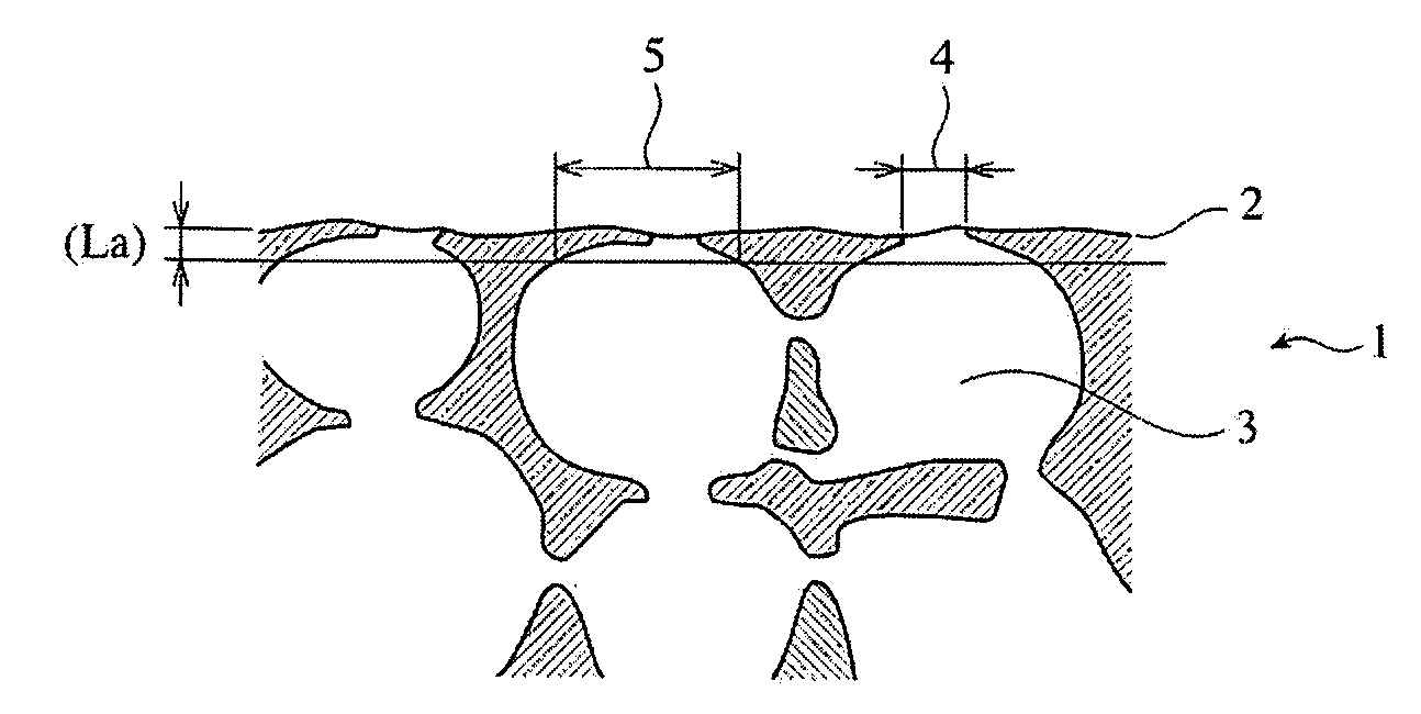
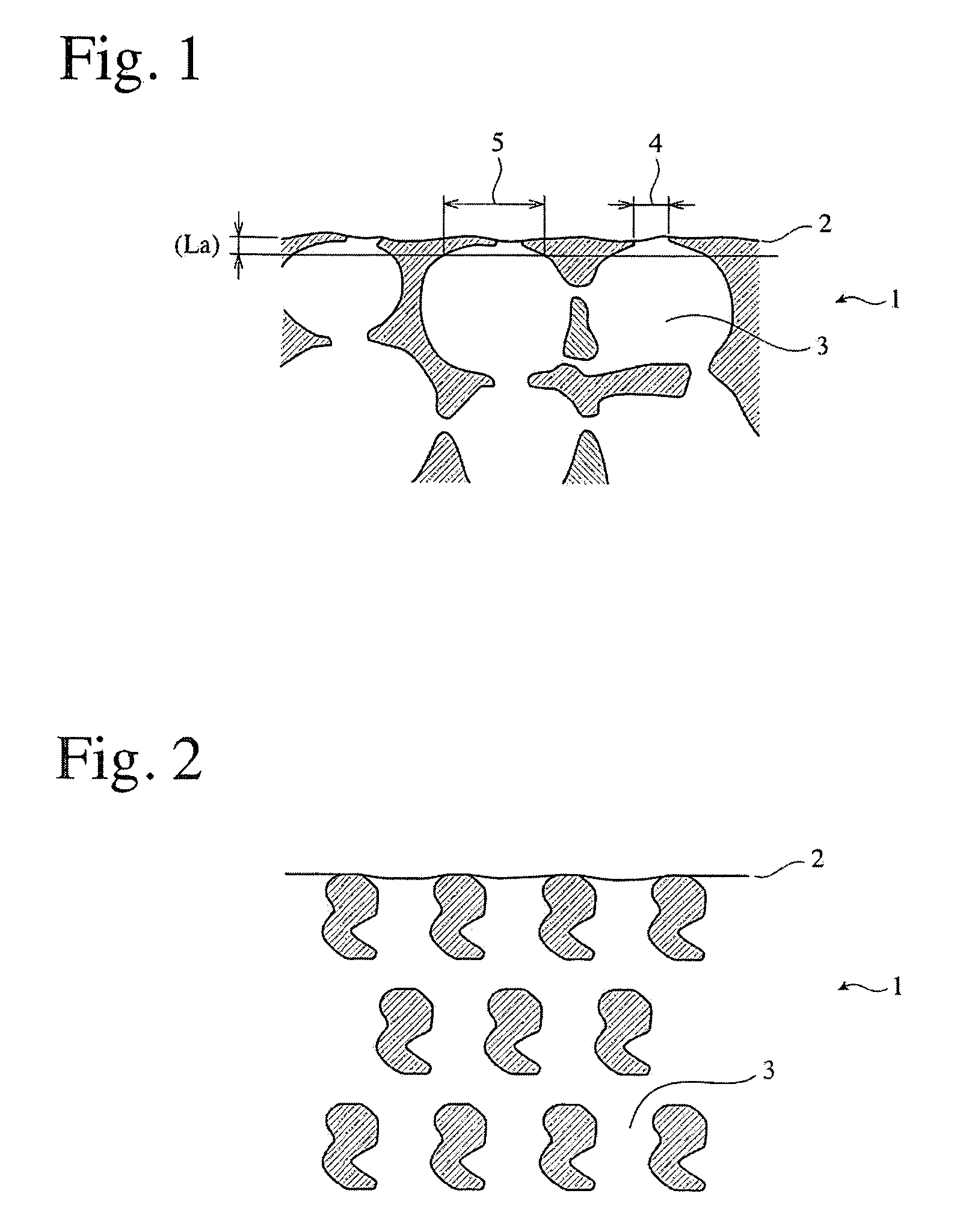
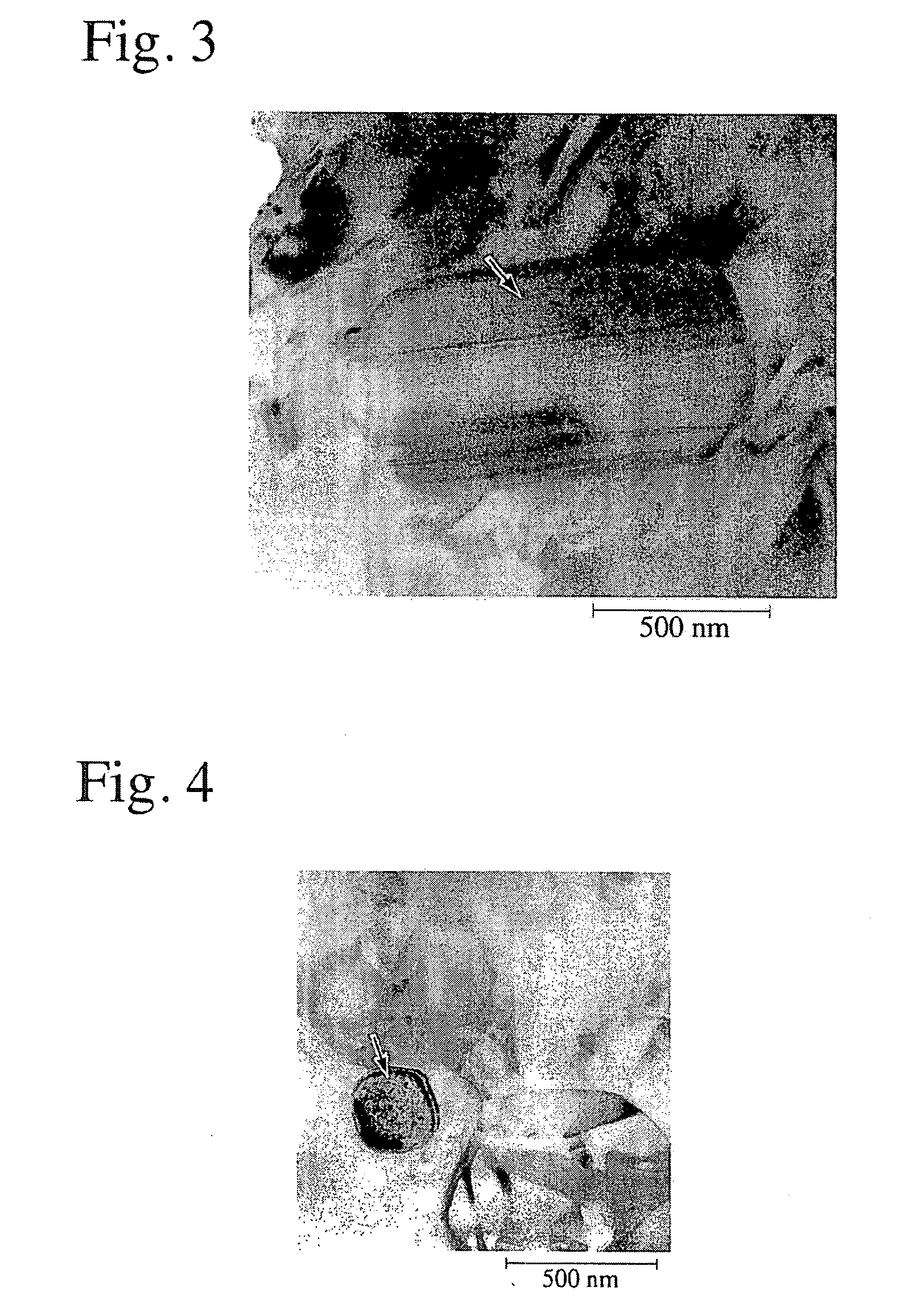
In a ceramic honeycomb structure having large numbers of flow paths partitioned by porous cell walls, the cell walls have a porosity of 55-75%, with an average pore diameter Da of 10-30 μm and a pore area ratio Sa of 10-30% on their surfaces, and the average length La of the pores at their openings and the average width Lb of the pores at depth La from the surfaces of the cell walls meet the condition of 1.1<Lb / La<5 in an arbitrary vertical cut surface of the cell walls. In the cordierite-based ceramic honeycomb structure, the ceramic contains Fe and a spinel, the amount of the spinel being 4% or less by an X-ray diffraction intensity ratio, and most of the spinel having particle sizes in a range of 0.01-5 μm.

Description

FIELD OF THE INVENTION[0001]The present invention relates to a ceramic honeycomb structure suitable for a ceramic honeycomb filter for capturing particulate matter such as fine carbon particles, etc. discharged mainly from diesel engines, and a moldable material usable for its extrusion molding.BACKGROUND OF THE INVENTION[0002]Attracting much attention as a ceramic honeycomb filter for capturing particulate matter contained in an exhaust gas from a diesel engine and burning the particulate matter by a heater or a burner disposed at a desired position is a ceramic honeycomb filter constituted by a ceramic honeycomb structure having flow paths partitioned by porous cell walls with predetermined flow paths plugged, a gas mainly passing through the porous cell walls. As shown in FIG. 5(a) and FIG. 5(b), a ceramic honeycomb filter 50 is usually a cylinder having a circular or elliptical cross section, which has a structure comprising a porous ceramic honeycomb structure 51 having periphe...

Claims


Application Information

Patent Timeline
Patent Type & Authority Patents(United States)
IPC IPC(8): B01D53/02B01D53/94C04B35/195C04B38/00F01N3/022
CPCB01D53/944C04B35/195C04B35/62625C04B38/0009F01N3/0222C04B38/0054C04B38/0074C04B2235/3206C04B2235/3217C04B2235/3218C04B2235/3222C04B2235/3272C04B2235/3418C04B2235/3445C04B2235/349C04B2235/5436C04B2235/5463C04B2235/6562C04B2235/72C04B2235/727C04B2235/75C04B2235/77C04B2235/785C04B2235/786C04B2235/787C04B2235/80C04B2235/96C04B2235/9607F01N2330/06C04B2111/00189C04B2111/00198Y02T10/20Y10S55/05Y02T10/12B01D39/02B01D39/20C04B38/00
Inventor KAWATA, TSUNEHIROTOKUDOME, OSAMUSUWABE, HIROHISASEKIGUCHI, KENICHIROYAMANE, HIDEYA
Owner HITACHI METALS LTD
Learn More