
Apparatus for microarray binding sensors having biological probe materials using carbon nanotube transistors

a technology of carbon nanotube transistors and microarrays, applied in thermoelectric device junction materials, diaphragms, immobilised enzymes, etc., can solve the problems of large amount of reagents, complex protocols, laborious techniques, etc., and achieve low ionic buffer, rapid hybridization, and limited sensitivity

Inactive Publication Date: 2011-09-13
UNIV OF MARYLAND +1
View PDF6 Cites 88 Cited by
  • Summary
  • Abstract
  • Description
  • Claims
  • Application Information

AI Technical Summary

Benefits of technology

This approach enhances sensitivity and simplifies the detection process, eliminating the need for labeling and optical detection, facilitating miniaturization and improving the throughput of DNA detection, making it suitable for various applications such as monitoring gene expression and detecting pathogens.

Problems solved by technology

A major hurdle of using DNA microarray as a clinical tool is that the technique is laborious, requires complex protocols, requires large amounts of reagents, and suffers from low signal to noise ratio and rapid optical degradation.
While significant strides have been made in fluorescent-based DNA microarray technology, the methodologies are often time-consuming and in addition rely on the determination of fluorescence intensity and the sensitivity is thus limited by the ability to detect small numbers of photons.
Moreover, fluorescent molecules suffer from photobleaching, which means that the fluorescent molecule will stop to fluoresce after receiving a certain amount of excitation.
These methods are both time consuming and afford limited sensitivity.
While this technique is highly sensitive, use of optical methods impedes progress in both system miniaturization and in direct interfacing with data collection electronics.

Method used


Image

  • Apparatus for microarray binding sensors having biological probe materials using carbon nanotube transistors
  • Apparatus for microarray binding sensors having biological probe materials using carbon nanotube transistors
  • Apparatus for microarray binding sensors having biological probe materials using carbon nanotube transistors

Examples


example 1

Use of Catalysts in Forming CNTs

[0228]At least two methods may be employed for creating Fe nanoparticles that act as catalysts for CNT growth: a). Ultra high vacuum deposition of Fe at a thickness of less than 0.5 nanometers; and b). Formation of FePt particles using “nanocluster gun” technique of Ping Wang at Univ. of Minnesota. FIGS. 24 and 25 show the growth of CNT for each catalyst. Both produce CNTs, but longer and sparsely distributed CNT's are formed on FePT clusters. Any conventional method for forming CNTs may then be used with the Fe-containing catalysts.

example 2

Gold Deposition to Connect NT Channel to S and D Electrodes

[0229]Gold contracts are made using standards contact photolithography techniques and depositing gold to the defined area using physical vapor deposition technique. Briefly, standard contact photolithography involves coating the substrate / sample with a light-sensitive material, or a photoresist, which dissolves or hardens depending on the type upon exposure to light and subsequent developer solution. Patterns from a pre-drawn mask are transferred to the photoresist by exposing it to an ultraviolet light through the mask. A physical vapor deposition technique involves vaporizing solid material of interest, which is gold for this particular purpose, through various methods such as: resistive heating, electron beam heating, plasma sputtering, such that the vapor condenses on the substrate / sample thereby creating a thin film on the substrate / sample. Gold adhesion towards the oxide substrate / sample is improved by first depositing...

example 3

Preparation of Aluminum Oxide Gate Material

[0230]A preferred method for creating oxides, such as aluminum or hafnium oxides is by atomic layer deposition. Atomic layer deposition (ALD) is a known deposition method in which a film is built up one atomic layer at a time by saturating the functional group of the surface with a suitable precursor. The ALD cycle / steps to deposit aluminum oxide starts by saturating the surface, which inevitably contains hydroxyl group due to air moisture, with trimethyl aluminum (TMA). After excess / unreacted trimethyl aluminum is removed, water vapor is introduced to convert the methyl group of TMA to hydroxyl group, releasing methane as the byproduct. The newly converted hydroxyl group is now ready to react with another cycle of TMA exposure. Cycles of introduction of TMA and water vapor are repeated until the desired thickness is achieved.


PUM

PropertyMeasurementUnit
separation distanceaaaaaaaaaa
thickaaaaaaaaaa
temperatureaaaaaaaaaa

Abstract

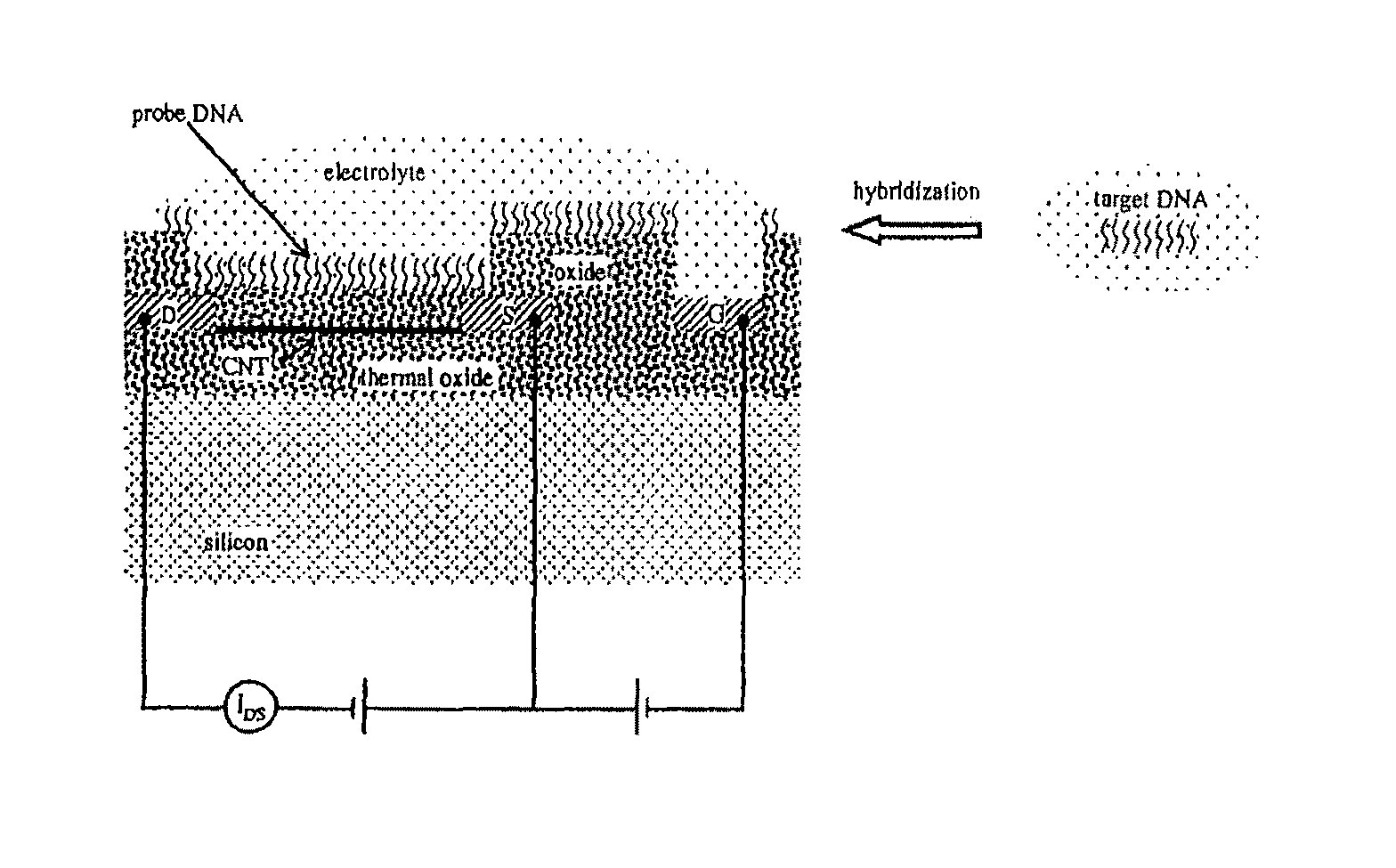
A microarray apparatus is provided which contains at least one chip having source and drain electrodes positioned on an array of carbon nanotube transistors which allows for electronic detection of nucleic acid hybridizations, thereby affording both increased sensitivity and the capability of miniaturization.

Description

CROSS REFERENCE TO RELATED CASES[0001]This application claims the benefit of Provisional U.S. Application Ser. No. 60 / 743,524, filed Mar. 17, 2006, which is incorporated by reference herein in its entirety.STATEMENT REGARDING FEDERALLY SPONSORED RESEARCH[0002]The work leading up to the present invention was funded, at least in part, by NSA under Grant H9823004C0470. As such, the U.S. Government may have certain rights in the present invention under the provisions of 35 U.S.C. 203 et seq.BACKGROUND OF THE INVENTION[0003]1. Field of the Invention[0004]The present invention relates to an apparatus containing microarray binding sensors having biological probe materials using carbon nanotube transistors and various methods for detecting binding of biological target materials thereto.[0005]2. Description of the Background[0006]DNA microarrays are powerful tools in molecular biology, and generally contain an array of hundreds to tens of thousands of genes spotted on a solid substrate, and ...

Claims


Application Information

Patent Timeline
Patent Type & Authority Patents(United States)
IPC IPC(8): H01L51/10H01L51/30
CPCB82Y15/00B82Y30/00G01N33/5438Y10S977/92Y10S977/938Y10S977/702
Inventor GOMEZ, ROMEL DEL ROSARIOKHAN, JAVEDPANDANA, HERMANASCHENBACH, KONRADFUHRER, MICHAELWEI, JUN STEPHEN
Owner UNIV OF MARYLAND
Learn More