Bone implant with osteo-inducing structure

a bone implant and osteo-induction technology, applied in the field of transforaminal lumbar interbody fusion implant, can solve the problems of inability to easily insert devices into the affected disk space, post-surgical pain, and injuring or degrading the major back muscles, so as to promote osteo-induction, promote growth and fusion of patient bone, and promote osteo-induction

Inactive Publication Date: 2011-10-25
AESCULAP IMPLANT SYST
View PDF2 Cites 46 Cited by
  • Summary
  • Abstract
  • Description
  • Claims
  • Application Information

AI Technical Summary

Benefits of technology

[0010]These needs are met by the invention, which provides multiple bone graft segments to allow matching of different interverbral separations, provides a plurality of voids and perforation channels to promote osteo-induction, and manifests mechanical strength sufficient to withstand the maximum likely compression stress that a portion of a spine may experience. The multiple bone segments interlock together, and no bone pins are required. The voids and perforation channels serve as centers for bone induction, and the bone graft promotes growth and fusion of patient bone at and adjacent to the bone implant location, by promoting osteo-induction. The system is stable against very high stress compression, extrusion and rotation of one or more bone implant segments. Optionally, each segment has at least one perforation channels and / or a void that communicates with a perforation channel and / or a void of one or more adjacent segments, to promote osteo-induction.
[0011]The invention is an intervertebral implant system using autograft, allograft or xenograft components for transforaminal lumbar interbody fusion (TLIF) surgery. In a preferred embodiment, the TLIF procedure uses one or more curvilinear delta shaped implant segments, with curved features at corners of the device. Use of a rounded delta shape provides a TLIF implant with anatomically safe insertion during surgery. The superior and inferior segments that fuse on the vertebral end plates are complementary and have appropriate concave, convex and chamfer features. Concave and convex features are selected to closely match anatomical shapes of the vertebral end plates. Inclusion of a chamfer feature ensures safe insertion of the device into the affected disk space. Surfaces for the superior and inferior segments have a small, positive lordosis angle (e.g., about 1-8°, preferably about 5°) for recovery of lumbar lordosis curvature.
[0012]The bone graft system preferably includes two or more implant segments that join or interlock together without requiring use of bone pins or similar attachment components. Sizeable voids and / or perforation channels are provided near a center of a bone graft. These voids receive the perforation channels and serve as centers for bone induction, and the bone graft promotes bone growth and fusion at the implant location, through promotion of osteo-induction. This action provides stability against compression, shifting (translation) and rotation after implantation. Interlocking of segments occurs through provision of complementary male and female shapes with improved interference fit of the complementary shapes. Optional chamfered surfaces facilitate fabrication and placement of a segment.

Problems solved by technology

However, several studies have shown that extensive surgical exposure for extended time periods (hours) can seriously injure or degrade the major back muscles and can cause post-surgical pain.
In a TLIF procedure, several traditional PLIF implant devices, such as threaded titanium or stainless steel cages, allograft wedges and rings have been used, with mixed results.
However, these devices are not easily inserted into the affected disk space and may produce temporary or permanent nerve damage.
However, an implant system based on natural bone substances may not withstand the estimated 500-1500 Newtons / cm2 pressure to which portions of a spine are subjected.
One problem with provision of a plurality of perforation channels is that these channels may reduce mechanical strength of the resulting structure.
This approach appears to provide the required mechanical strength but does not appear to encourage osteo-induction at the interface of the bone fragments; the bone fragments remain separate, with little or no prospect of fusion.

Method used


Image

  • Bone implant with osteo-inducing structure
  • Bone implant with osteo-inducing structure
  • Bone implant with osteo-inducing structure

Examples


Embodiment Construction

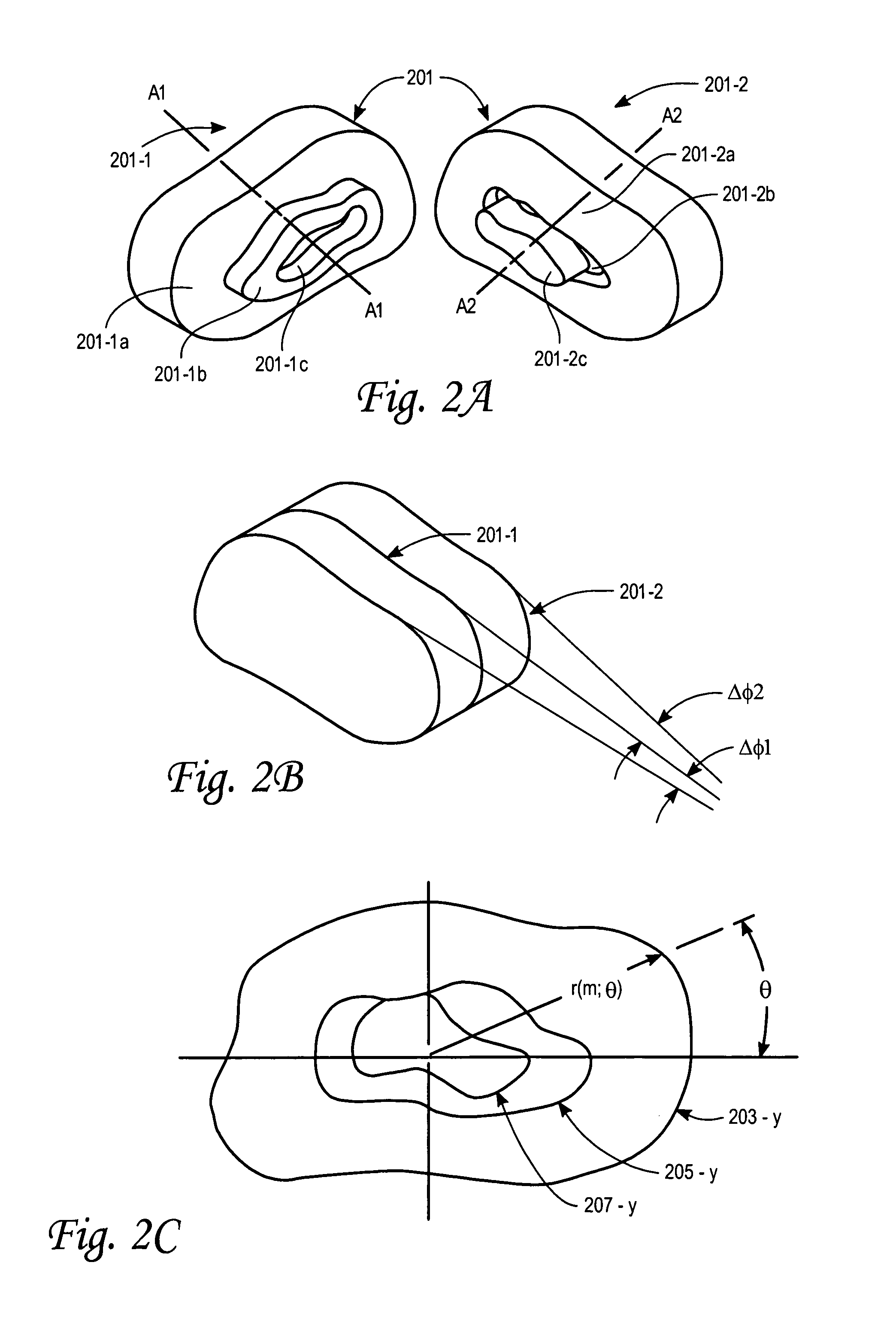
[0024]FIG. 2A illustrates two segments, 201-1 and 201-2, having respective axes A1-A1 and A2-A2, according to one embodiment of the invention, which can be coupled or fitted together along a common axis to form an interlocking bone graft implant system, as illustrated in FIG. 2B. The bone implant segment 201-1 includes a first female annular region 201-1a, surrounding a second male annular region 201-1b, which in turn surrounds a third female annular region 201-1c. These annular regions may be, but need not be, cylindrically symmetric. The bone implant segment 201-2 includes a first male annular region 201-2a, surrounding a second female annular region 201-2b, which in turn surrounds a third male annular region 201-2c. Preferably, the material used here is predominantly cortical bone, although cancellous bone and other natural bone substances can also be used.

[0025]The implant segments 201-1 and 201-2 fit together so that the first female annular region 201-1a receives the first mal...


PUM


Abstract

A spine implant system having two or more adjacent segments that have a male-female annular interlocking relationship for increased mechanical stability and resistance to relative translation and rotation. One or more segments is provided with at least one perforation channel or void to promote osteo-induction within the segment. Optionally, two adjacent segments have at least one common or aligned perforation channel or void. Two or more spaced apart portions of a segment surface are optionally chamfered to provide easier fabrication and / or positioning of the segment. Two spaced apart exposed surface planes of an interlocked segment pair optionally are axially oriented at a small positive angle relative to each other, to approximate natural spine curvature. Segments in some embodiments have a curvilinear delta cross sectional shape and / or have crosshatched grooves in exposed surfaces. Many of the embodiments are useful in transforaminal lumbar interbody fusion (TLIF).

Description

FIELD OF THE INVENTION[0001]This invention relates to inter-body spinal fusion bone grafts with multiple segments, and more particularly a transforaminal lumbar interbody fusion implant.BACKGROUND OF THE INVENTION[0002]A spine of a vertebrate animal, including a human, has a space between adjacent vertebrae, referred to as the “inter-body space” of the spine. This space is occupied by a disk including an annulus of firm material, surrounding a moist, mushy central material that is called the nucleus. This space separates and cushions adjacent vertebrae. Medical conditions of degenerative disk disease that cause severe back pain include herniated nucleus pulposis and collapse disk space that cause compression of spinal cord roots. Intervertebral spinal fusion is a surgical technique that often relieves back pain arising from these medical conditions, by removing an affected disk, fusing two adjacent vertebral bodies together and by inserting one or more implants that allow bone to gr...

Claims


Application Information

Patent Timeline
Patent Type & Authority Patents(United States)
IPC IPC(8): A61F2/44
CPCA61F2/4465A61F2002/2835A61F2002/30329A61F2002/30352A61F2002/3036A61F2002/30362A61F2002/30367A61F2002/3054A61F2002/30543A61F2002/30599A61F2002/30604A61F2002/30616A61F2002/30785
Inventor PARK, ILWHANLO, JANZENKOZAK, JEFFREYBURCKHARDT, OLIVER
Owner AESCULAP IMPLANT SYST
Why Eureka
Try Eureka