
Image forming apparatus

Inactive Publication Date: 2011-11-15
RICOH KK
View PDF63 Cites 0 Cited by
  • Summary
  • Abstract
  • Description
  • Claims
  • Application Information

AI Technical Summary

Benefits of technology

[0012]Because of these reasons, the present inventors recognize that a need exists for an image forming apparatus which can restrain deterioration of electric characteristics of an image bearing member for repetitive use for a long period of time, have an excellent mechanical durability and stably produce quality images.
[0013]Accordingly, an object of the present invention is to provide an image forming apparatus which can restrain deterioration of electric characteristics of an image bearing member for repetitive use for a long period of time, have an excellent mechanical durability and stably produce quality images.

Problems solved by technology

Among these, electron transfer materials are demanded because the above-mentioned structure is positively charged, meaning generation of ozone and non-uniformity of charging are little in comparison with negative charging.
However, it is extremely difficult to find excellent electron transfer materials as materials for an image bearing member.
For example, there are materials having excellent electron transfer properties with a problem about safety, for example, mutagenic property.
Such materials are not suitable for practical use.
Such a material is dissolved over time so that the characteristics thereof deteriorate.
This leads to degradation of image quality due to extreme deterioration of electric characteristics over repetitive use.
The issue is that the quality of images is initially good but deteriorates over a long period of time.
However, such additives inhibit electron transfer property inherently seen in an electron transfer material.
This causes a side effect, for example, deterioration of sensitivity characteristics.
When the addition amount of such an additive increases, a binder resin becomes brittle.
This reduction in strength leads to deterioration of anti-abrasion property.
Consequently, there is no image forming apparatus which produces quality images for a long-time repetitive use.

Method used


Image

  • Image forming apparatus
  • Image forming apparatus
  • Image forming apparatus

Examples


example 1

[0134]The image bearing member prepared for Example 1 as described above is installed in a digital multi-function machine remodeled based on imagio MF2230, (manufactured by Ricoh, Co., Ltd.) with such a change that the power supply is changed and the power supply is changed and the charging polarity is changed to positive polarity for evaluation.

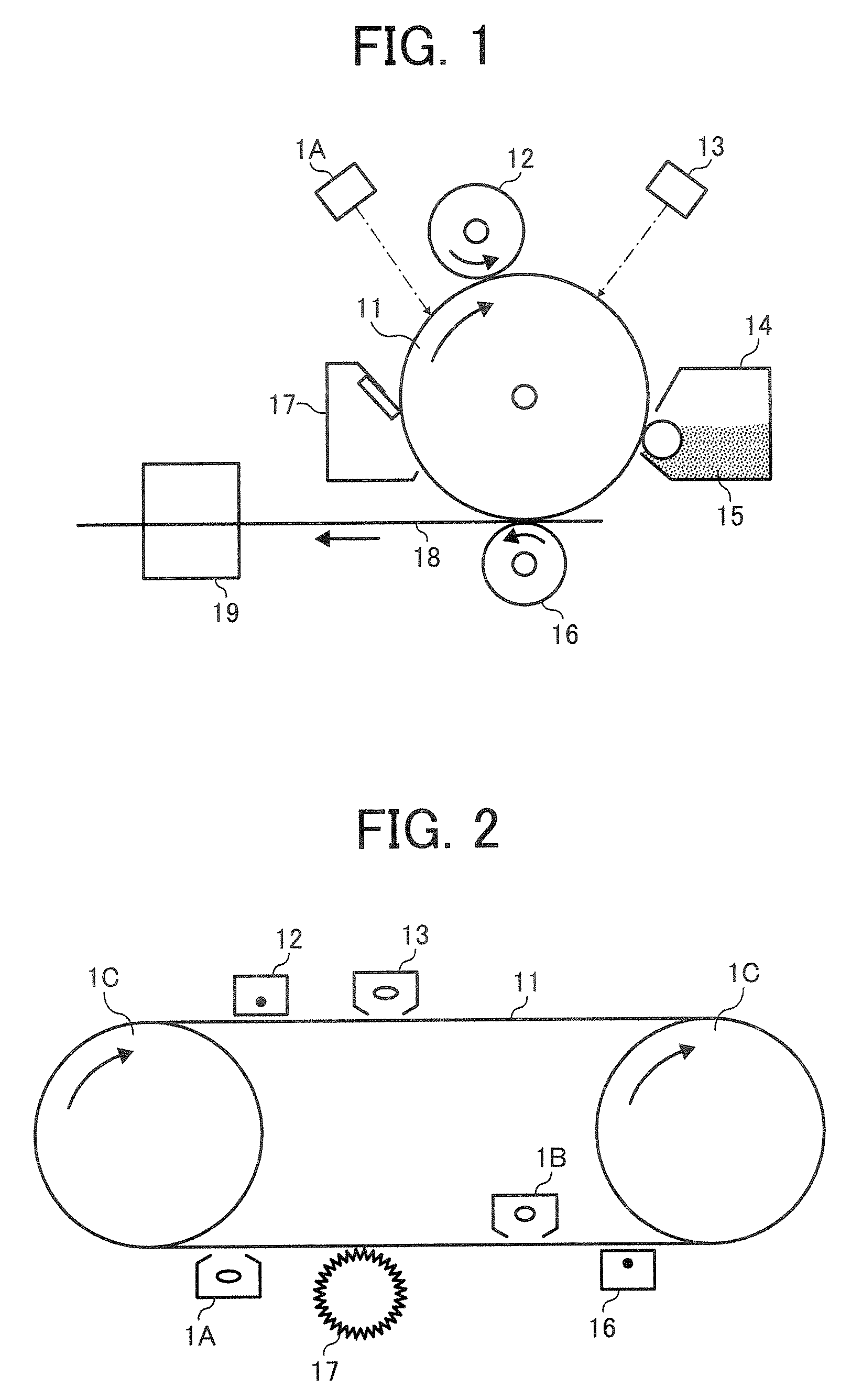
[0135]A laser diode (LD) of 780 nm is used as the writing image irradiation unit in this image forming apparatus. A light-emitting diode (LED) of 660 nm is used as the discharging irradiation unit (hereinafter referred to as discharging device) for discharging performed after transfer and before charging.

[0136]With this image forming apparatus, photocopying tests are performed and after the initial copy and 10,000th copy, evaluation is made for the following items.

Voltage at Irradiated Portion

[0137]The voltage at irradiated portions when a solid image is written is evaluated under the condition of the initial surface voltage (charging voltag...

synthesis example 1

of Titanyl Phthalocyanine for Use in Image Bearing Member for Example 2

[0141]A pigment is prepared according to JOP 2001-19871 as follows: Mix 29.2 g of 1,3-diiminoisoindoline and 200 ml of sulfolane; Drop 20.4 g of titanium tetrabuthoxido to the mixture in a nitrogen atmosphere; Subsequent to dropping, heat the resultant gradually to 180° C.; Stir the resultant for 5 hours for reaction while keeping the reaction temperature between 170 to 180° C.; After the reaction, cool down the resultant for precipitation and filter the precipitated material; Wash the filtered material with chloroform until the obtained powder becomes blue; Wash the powder with methanol several times; Wash the resultant with 80° C. hot water followed by drying to obtain coarse titanyl phthalocyanine: Dissolve the coarse titanyl phthalocyanine in concentrated sulfuric acid in an amount of 20 times the weight of the coarse titanyl phthalocyanine: Drop the resultant to iced water in an amount of 100 times the amoun...

example 7

[0160]Example 7 is performed and evaluated in the same manner as in Example 2 except that the image irradiation light source for use in the image forming apparatus for the evaluation is changed from the LD unit of 780 nm to an LD unit of 655 nm.


PUM


Abstract

An image forming apparatus having an image bearing member having a substrate and a photosensitive layer having a charge generating layer and a charge transport layer, a charging device for uniformly charging the surface of the image bearing member, an irradiating device having a light source for irradiating the image bearing member to form a latent electrostatic image thereon, a developing device for developing the latent electrostatic image, a transfer device for transferring the developed image to a recording medium and a cleaning device for cleaning the surface of the image bearing member, wherein the charge transport layer contains a charge transport material represented by the following chemical formula, the light source emits light having a wavelength not less than 600 nm and the image bearing member is not irradiated with light having a wavelength less than 600 nm,wherein R1 and R2 independently denote a hydrogen atom, a substituted or non-substituted alkyl group, a substituted or non-substituted cycloalkyl group, a substituted or non-substituted aralkyl group, R3, R4, R5, R6, R7, R8, R9 and R10 independently denote a hydrogen atom, a halogen atom, cyano group, nitro group, amino group, hydroxyl group, a substituted or non-substituted alkyl group, a substituted or non-substituted cycloalkyl group, a substituted or non-substituted aralkyl group.

Description

BACKGROUND OF THE INVENTION[0001]1. Field of the Invention[0002]The present invention relates to an image forming apparatus.[0003]2. Discussion of the Background[0004]As an image bearing member for use in an image forming apparatus applied to a photocopier and a laser printer, inorganic image bearing members formed of, for example, selenium, zinc oxide and cadmium sulfide, used to be widely used. However, in terms of the reduction of burden on environment, cost reduction and design latitudes, organic image bearing member (e.g., organic photoconductors (OPC)) have been diffusing now.[0005]This organic image bearing member can be classified by layer structure. For example, organic image bearing members can be typified into (1) uniform single layer type, in which photoconductive resin (e.g., polyvinyl carbazol (PVK)) or charge transfer complex ((e.g., PVK-TNF (2,4,7-trinitrofluorenone)) is provided on an electroconductive substrate, (2) dispersion single layer type, in which a dispersi...

Claims


Application Information

Patent Timeline
IPC IPC(8): G03G15/00
CPCG03G5/0651G03G5/0696G03G15/011
Inventor KURIMOTO, EIJISHIMOYAMA, KEISUKEKAWAMURA, SHINICH
Owner RICOH KK
Learn More