
Chemical analyzer for industrial process control

a technology of industrial process control and chemical analyzer, which is applied in the direction of optical radiation measurement, instruments, spectrometry/spectrophotometry/monochromator, etc., can solve the problems of not working well, limiting the type of sensors to the measurement, and failing to meet the needs of homonuclear species such as nitrogen, oxygen, chlorine, hydrogen and fluorine that cannot, etc., to achieve the effect of maximizing optical throughput, low cost and robustness

Active Publication Date: 2011-12-13
CAMBRIUS
View PDF26 Cites 11 Cited by
  • Summary
  • Abstract
  • Description
  • Claims
  • Application Information

AI Technical Summary

Benefits of technology

"The present invention is a small and affordable photometric analyzer that can measure the chemical composition of industrial process samples. It uses Raman scattering to measure the analytes without extracting or redirecting material from the process. The analyzer can analyze chemical concentrations remotely from the process, making it suitable for a wide range of conditions. It is customizable for specific applications by identifying which chemical species to measure. The technical effects of the invention include increased optical throughput, improved signal-to-noise ratio, and on-board quantification of process concentrations."

Problems solved by technology

The method works well for many species, but fails for homonuclear species such as nitrogen, oxygen, chlorine, hydrogen, and fluorine that cannot have a net change in dipole moment.
These types of sensors are typically limited to the measurement of a single species and often supplement IR methods.
As a result, Raman spectrometers have found a niche in the market where no other viable solutions exist.
Despite these advantages, broad adoption of Raman spectrometers has been hindered because they are very expensive to buy, install and maintain, require frequent calibrations and skilled operators and, in general, lack the robustness necessary to operate in harsh plant environments.
Fiber optic couplers are known to limit optical throughput.

Method used


Image

  • Chemical analyzer for industrial process control
  • Chemical analyzer for industrial process control
  • Chemical analyzer for industrial process control

Examples


Embodiment Construction

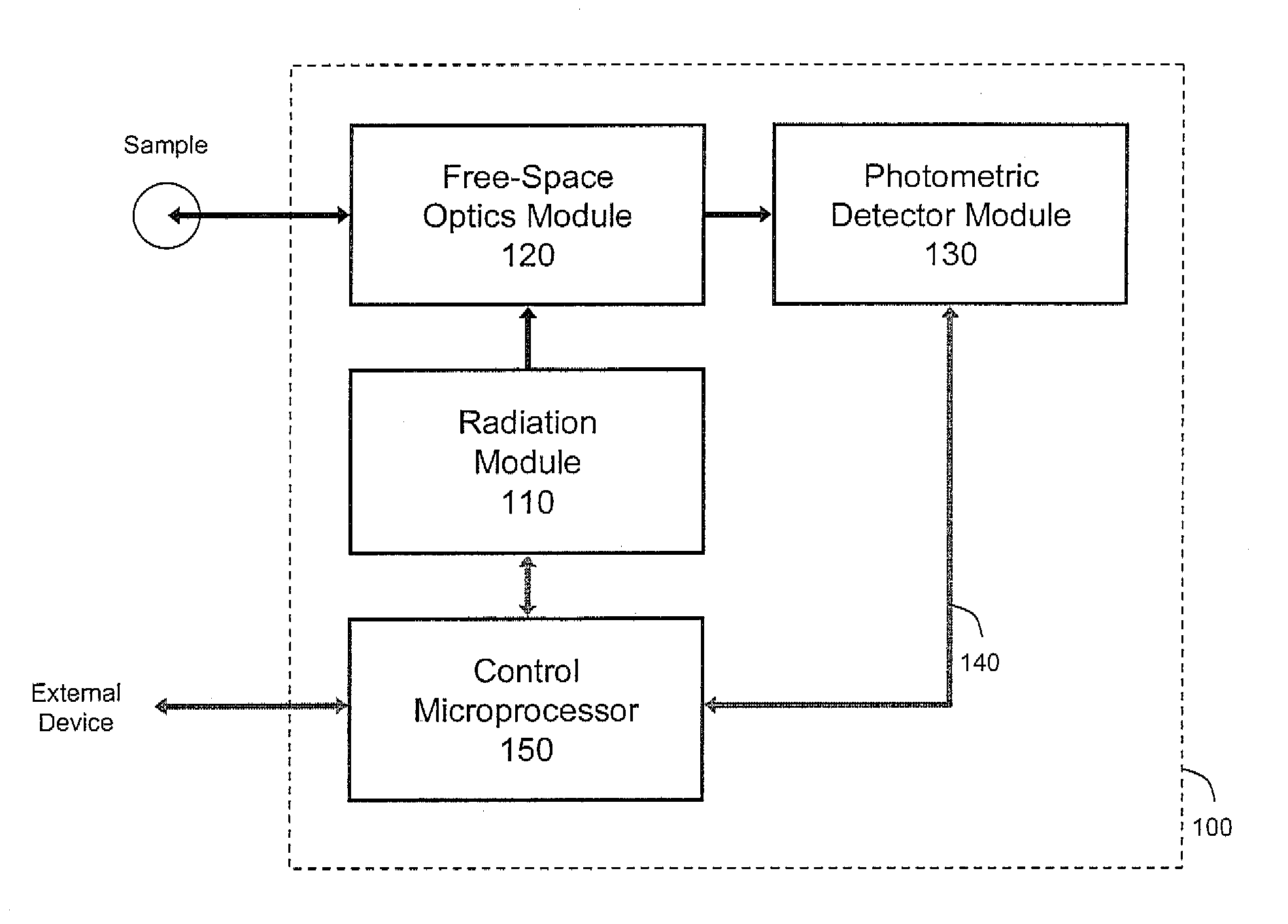
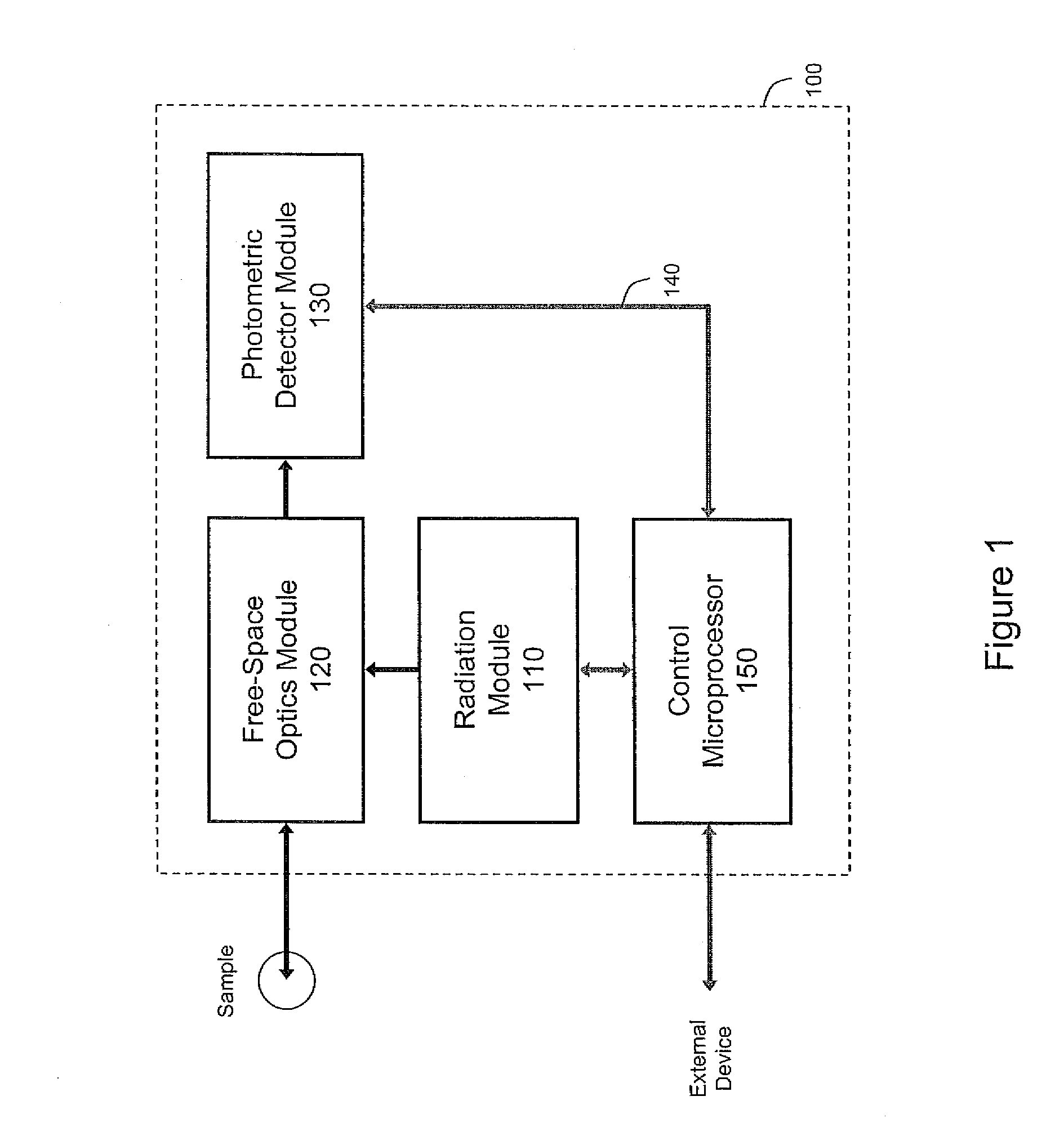
[0018]A schematic representation of the invention is shown in FIG. 1. The black arrows indicate the direction of the primary optical signals; the gray arrows indicate the direction of the primary electrical signals. A radiation module 110 which includes a laser radiation source is controlled by a control microprocessor 150. The laser source can be of any type but is preferably a solid state laser diode. In a preferred embodiment of the invention, the laser radiation source emits radiation primarily at a wavelength of 785 nm.

[0019]After leaving the radiation module, the laser radiation is transferred via free-space optics to a free-space optics module 120. In a preferred embodiment of the invention, the optics module includes a selective reflector which treats the laser radiation differently than other radiation, in particular the radiation that comprises the return signal (defined below). The selective reflector may reflect the laser radiation while allowing other radiation to pass ...


PUM


Abstract

An optical apparatus for measurement of industrial chemical processes. The analyzer uses Raman scattering and performs measurement of chemical concentrations in continuous or batch processes. The analyzer operates at a standoff distance from the analyte (or analytes) and can measure concentrations through an optical port, facilitating continuous, non-destructive, and non-invasive analysis without extracting the analyte or analytes from the process. The analyzer can measure one or several solid, liquid, or gaseous analytes, or a mixture thereof.

Description

BACKGROUND OF THE INVENTION[0001]Defined as the analysis of material properties in industrial manufacturing processes, process analysis has been performed for several decades in a wide variety of industries. These industries include chemical, petrochemical, petroleum, pharmaceutical, food & beverage, pulp & paper, and agricultural. A former common implementation of process analysis consisted of manually extracting samples from a process and carrying the samples to a laboratory for analysis. Over time, process analysis evolved from off-line analysis to a continuous on-line analysis where samples are extracted by automated sampling systems and carried in slip streams to process analyzers.[0002]The primary advantage of on-line process analysis is the reduction of the time interval between sample extraction and data generation. The faster response time provides greater control of manufacturing processes leading to increased product yield, improved product quality (consistency), reduced ...

Claims


Application Information

Patent Timeline
Patent Type & Authority Patents(United States)
IPC IPC(8): G01J3/44
CPCG01J3/02G01J3/0262G01J3/0286G01J3/0291G01J3/10G01J3/26G01J3/36G01J3/44G01N21/65G01J3/0208G01N2201/067G01J2003/1269G01N2021/1793G01N2021/8416G01N2201/0245
Inventor BROWN, GORDON C.BURKA, MICHAELCRANTON, BRIANERICKSON, DAVIDGRASSI, JAMESHAMMOND, MATTHEW PATRICKSHAFFER, MAXIMILLAN BENVILLENEUVE, PIERRE
Owner CAMBRIUS
Learn More