Thermal energy storage materials

a technology of energy storage materials and materials, applied in the direction of stationary plate conduit assemblies, indirect heat exchangers, lighting and heating apparatus, etc., can solve the problems of complex effort to apply tesms in commercial applications, complex assembly of such tesms into functionally operative systems, and inability to achieve satisfactory service performance, etc., to achieve the effect of improving performan

Inactive Publication Date: 2012-01-10
DOW GLOBAL TECH LLC
View PDF72 Cites 13 Cited by
  • Summary
  • Abstract
  • Description
  • Claims
  • Application Information

AI Technical Summary

Benefits of technology

[0009]The TESM system may include a TESM according to the present teachings in a container (e.g., a capsule), optionally being substantially free of any water and / or hydrogen in some other form, which has an interior wall including a metal oxide that has substantially no thermodynamic reaction with the TESM in service conditions. One particularly preferred TESM includes two metal containing compounds, each including a cation selected from lithium or sodium, and an anion selected from nitrate or nitrite. The TESM may include one or more other agents that improve its performance, such as a thermal conductivity promoter, a corrosion inhibitor, a nucleator, or any combination thereof. The TESMs exhibit any of a number of other attractive characteristics. For example, the TESM may have a value of Hc50 / HC1 greater than 70%, where Hc50 is defined as the quenched heat of crystallization measured by differential scanning calorimetry at a cooling rate of about 50° C. / min over a temperature range of TL+50° C. to TL−100° C. and HC1 is defined as the slow cooled heat of crystallization measured by differential scanning calorimetry at a cooling rate of about 1° C. / min. The TESM may have a liquidus temperature which is less than Tmin−25° C., wherein Tmin is the lowest melting temperature of any binary salt which can be formed by any anion of the TESM and any cation of the TESM. Other beneficial aspects will be gleaned from the teachings that follow.

Problems solved by technology

Heretofore, efforts to apply TESMs in commercial applications have also been complicated by difficulties in achieving satisfactory performance in service.
Though a TESM may be known to have certain attributes to qualify it as a heat storage material, the assembly of such TESMs into a functionally operative system has been complicated by the unpredictability of the materials and other considerations, such as TESM interactions in service with other system materials.
Many materials known to be phase change materials are also corrosive in many environments.
It may also prove difficult to predict how mixtures of such materials will fare in a desired application.
Considerations such as the compatibility of TESMs with these devices potentially can significantly deteriorate the performance of a particular TESM, even though the TESM is regarded theoretically as a good performing TESM.
For example, some water-containing TESMs have been observed to cause relatively rapid corrosion of device packaging.
Unpredictable kinetics also have complicated the adaptation of various TESM material systems, as has been durability in the face of intensive thermal cycling.

Method used


Image

  • Thermal energy storage materials
  • Thermal energy storage materials
  • Thermal energy storage materials

Examples


example 1

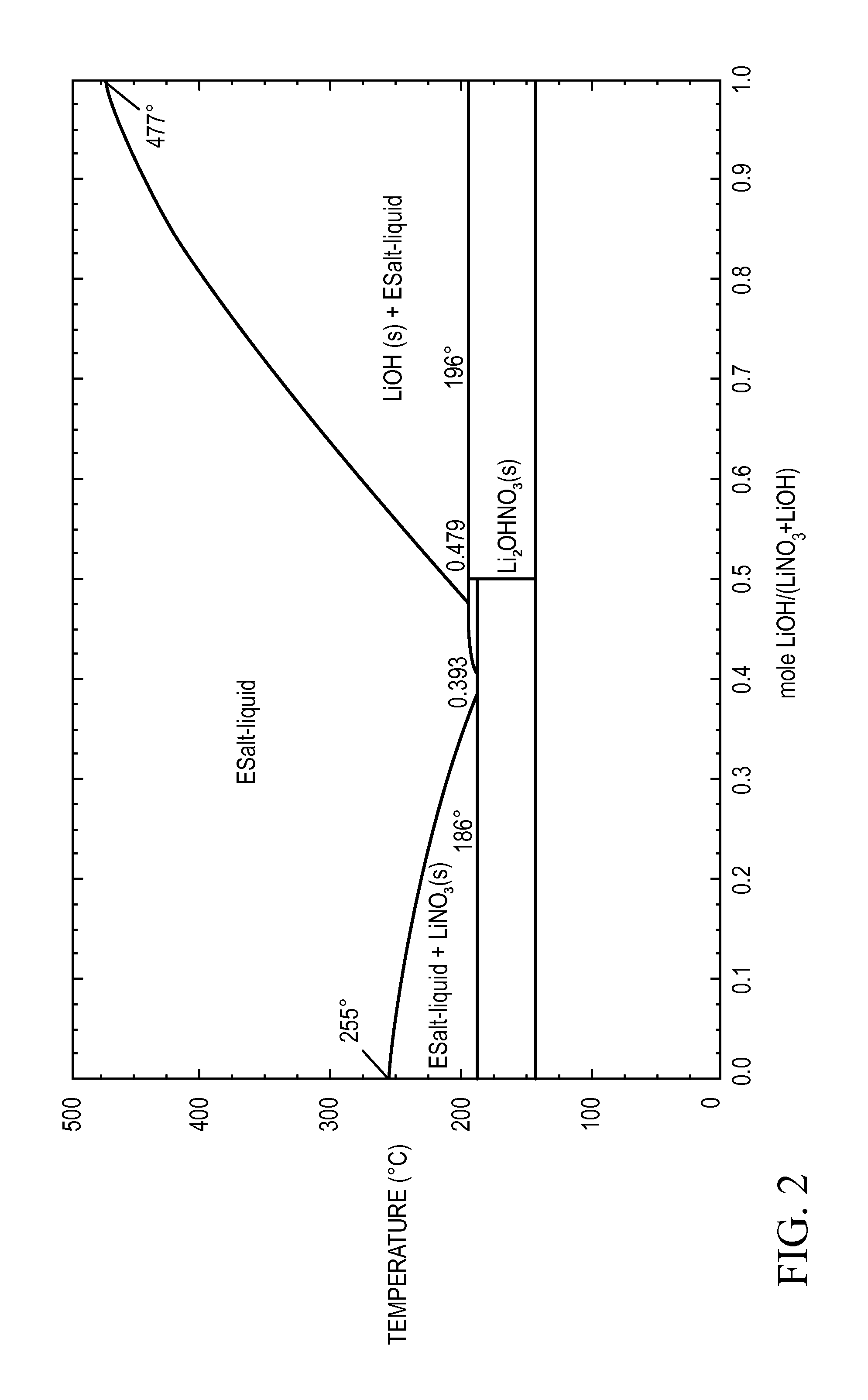
[0091]A 5 g mixture containing 40 mole % of powdered lithium nitrate and 60 mole % of powdered lithium hydroxide is prepared by first mixing wet grinding and mixing the two anhydrous salts with a mortar and pestle in acetone. The acetone slurry is then poured into a fused silica crucible with a fused silica lid, both lined with aluminum foil. After vacuum drying at room temperature to remove the acetone, the crucibles are placed in a furnace and heated from room temperature to 300° C. at a rate of 5° C. / min. The samples are held at 300° C. for 1 hour. While at the elevated temperature, the samples are stirred about every 5 minutes by shaking the entire furnace. These binary mixtures of lithium nitrate and lithium hydroxide are then cooled to room temperature. The liquidus temperature and the heat storage density from 300° C. to 80° C. of these samples is then measured. The heat storage density (HSD300,80) is greater than 1.4 MJ / l and the liquidus temperature is about 190° C.

example 2

[0092]A 5 g mixture of 85 mole % lithium nitrate and 15 mole % of an eutectic mixture of a mixed metal fluoride salt containing MgF2, NaF, and LiF (having a ratio of MgF2:NaF:LiF of about 10:43:47 and a eutectic transition temperature of about 630° C.) is prepared in a manner similar to Example 1. To homogenize the metal salts, a furnace is heated to 500° C. at 5° C. / min, and is then held for 1 hour at 500° C. The mixed metal fluoride dissolves in the molten lithium nitrate under these conditions. The sample is then cooled to room temperature. The sample is polished in order to perform optical microscopy studies of the structure and for compositional analysis using electron microscopy. The liquidus temperature and the heat storage density from 300° C. to 80° C. of these samples is then measured. The heat storage density (HSD300,80) is greater than 1.6 MJ / l and the liquidus temperature is about 196° C.

example 3

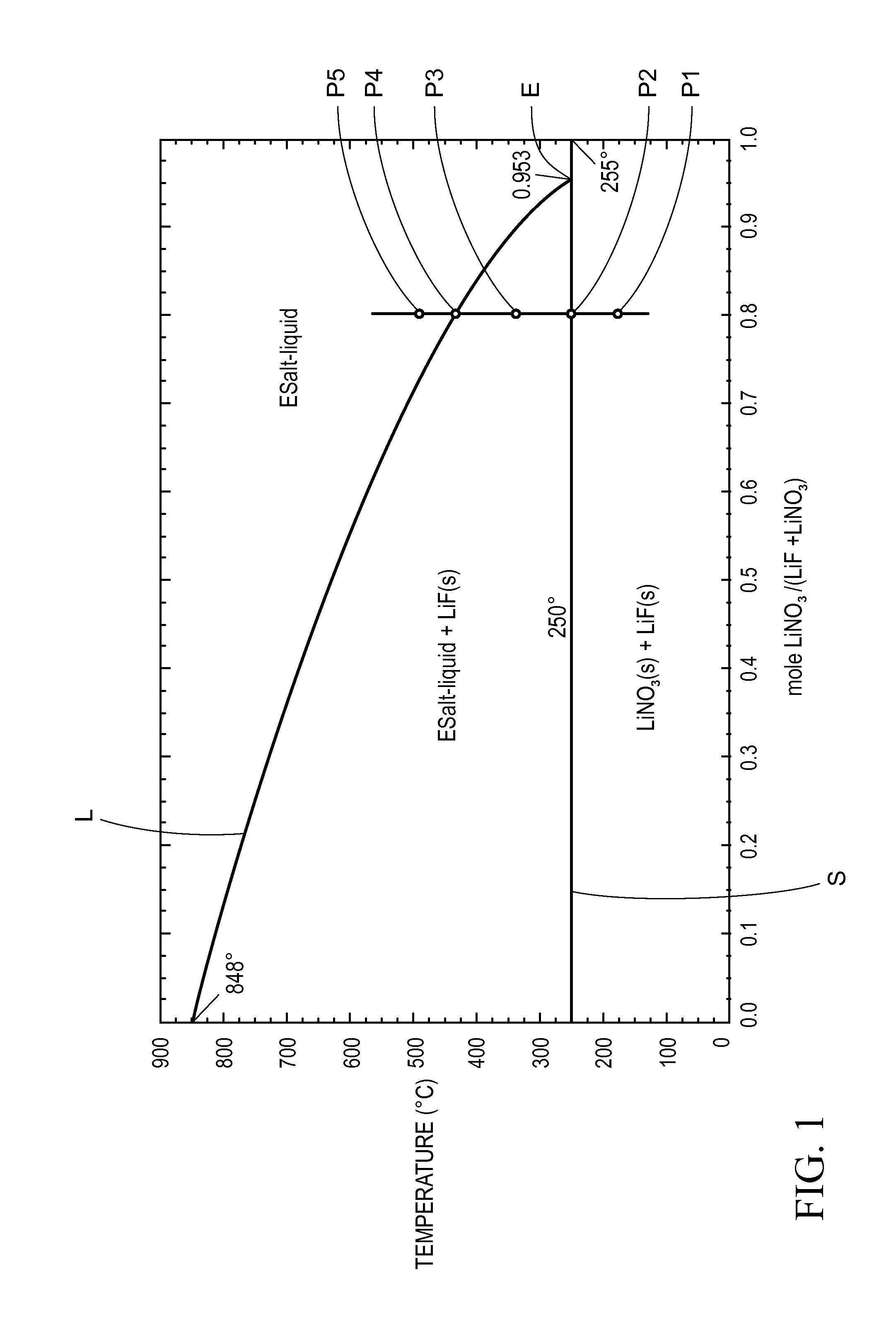
[0093]A 5 g mixture of 85 mole % lithium nitrate and 15 mole % of an eutectic mixture of a mixed metal salt containing NaCl, NaF, and LiF (having a ratio of NaCl:NaF:LiF of about 24:36:40 and a eutectic transition temperature of 582° C.) is prepared in a manner similar to Example 2. After homogenizing at 500° C. for 1 hour and cooling to room temperature this sample is polished in order to perform optical microscopy studies of the structure and for compositional analysis using electron microscopy. The liquidus temperature and the heat storage density from 300° C. to 80° C. of these samples is then measured. The heat storage density (HSD300,80) is greater than 1.4 MJ / l and the liquidus temperature is about 250° C.


PUM

PropertyMeasurementUnit
liquidus temperatureaaaaaaaaaa
volumeaaaaaaaaaa
liquidus temperatureaaaaaaaaaa

Abstract

The present invention relates to a thermal energy storage material (TESM) system (and associated methods) that reproducibly stores and recovers latent heat. The Thermal energy storage material system comprises i) at least one first metal containing material including at least one first metal compound that includes a nitrate ion, a nitrite ion, or both; and ii) at least one second metal containing material including at least one second metal compound. The thermal energy storage material system may water. If any water is present in the thermal energy storage material system, the water concentration should be less than about 10 wt. %. The thermal energy storage material has a liquidus temperature, TL, from about 100° C. to about 250° C. and exhibits a heat storage density from 300° C. to 80° C. of at least about 1 MJ / l, so that upon being used in a system that generates heat, at least a portion of the heat is captured and stored by the thermal energy storage material and subsequently released for use. The thermal energy storage material system is generally resistant to corrosion at temperatures of about 300° C. Exemplary metal compounds include one or more cations selected from the group consisting of Li, Na, K, Be, Mg, Ca, Al, and Ga.

Description

CLAIM OF PRIORITY[0001]The present application claims the benefit of the filing dates of U.S. Provisional Patent Application Nos. 61 / 030,755 (filed Feb. 22, 2008); 61 / 061,908 (filed Jun. 16, 2008); 61 / 074,799 (filed Jun. 23, 2008); 61 / 074,840 (filed Jun. 23, 2008); 61 / 074,869 (filed Jun. 23, 2008); 61 / 074,889 (filed Jun. 23, 2008); and 61 / 090,084 (filed Aug. 19, 2008), and U.S. patent application Ser. No. 12 / 389,598 entitled “HEAT STORAGE DEVICES” filed on Feb. 20, 2009, the contents of which are hereby incorporated by reference in their entirety.FIELD OF THE INVENTION[0002]The present invention relates to thermal energy storage materials (TESMs), and in one particular aspect, to improved TESM chemical compositions.BACKGROUND OF THE INVENTION[0003]Thermal energy storage materials (TESMs) are known and have been used in applications for storing heat for subsequent use. Many TESMs are phase change materials, meaning they undergo a phase change, typically between solid state and liquid...

Claims


Application Information

Patent Timeline
Patent Type & Authority Patents(United States)
IPC IPC(8): F28D17/00
CPCC09K5/063F24H7/02F28D9/0031F28D20/021Y10T29/49357F28F9/026Y02E60/145F28F2240/00F28D2020/0008Y02E60/14
Inventor BANK, DAVID H.SOUKHOJAK, ANDREY N.SEHANOBISH, KALYANMCLEOD, DAVID G.
Owner DOW GLOBAL TECH LLC
Why Eureka
Try Eureka