Dispersion compensator

a compensator and dispersion technology, applied in multiplex communication, instruments, optical elements, etc., can solve the problems of coupling loss, difficult to set a specified dispersion value to a desired arbitrary value, and insatisfactory, so as to facilitate the maintenance of the network system and the optical signal processor, reduce size, and simple free space optical system

Active Publication Date: 2012-09-04
NIPPON TELEGRAPH & TELEPHONE CORP
View PDF6 Cites 9 Cited by
  • Summary
  • Abstract
  • Description
  • Claims
  • Application Information

AI Technical Summary

Benefits of technology

[0012]The dispersion compensator shown in FIG. 31 has a size as large as 83 mm×83 mm including the 8-channel dispersion compensator array 41. A typical WDM system uses about 40 as the number of wavelengths. Accordingly, five dispersion compensator arrays 41 each configured as shown in FIG. 31 are required, and a large space is thus needed to implement the device. Furthermore, in the example configured as shown in FIG. 31, a phase shifter using a thermo-optic effect is used to implement the variability of the dispersion compensation characteristics, resulting in an increase in its power consumption.
[0016]The present invention was developed in view of these objects. It is thus an object of the present invention to realize a dispersion compensator capable of using small inexpensive optical components to set dispersion characteristics flexibly for each communication channel. This object also includes reducing the overall device size, decreasing its power consumption, eliminating loss, and improving optical characteristics such as maintaining the symmetry of transmitted spectra.
[0023]The dispersion compensator according to each of the aforementioned embodiments of the present invention preferably further includes a second dispersive element interposed between the cylindrical lens and the focusing lens, the second dispersive element having a second dispersion plane approximately orthogonal to the first dispersion plane of the arrayed-waveguide grating. The spatial light modulator can have two-dimensional pixels arranged repeatedly in a cyclic manner, respectively, along the first dispersion axis corresponding to the first dispersion plane and the second dispersion axis approximately orthogonal to the first dispersion axis corresponding to the second dispersion plane. This allows for setting an independent dispersion value freely for multiple communication channels.
[0027]Furthermore, the dispersion compensator further includes an optical tap having an output connected to an input of the dispersion compensator, and a wavelength demultiplexer having an input connected to an output of the dispersion compensator. In a network, the optical tap and the wavelength demultiplexer can be integrated with each other, thereby facilitating the maintenance of the network system and the optical signal processor.
[0028]As described above, according to the dispersion compensator of the present invention, existing general-purpose low-cost optical components can be combined to construct a relatively simple free space optical system. This structure allows for implementing a dispersion compensator to which flexible dispersion characteristics can be set in the case of a system change. The dispersion compensator features a reduced size, high flexibility of setting dispersion characteristics, and improved manufacturability. Even when WDM wavelengths are relocated due to changes in system operation, it is possible to change the system configuration in a flexible manner and facilitate its maintenance.

Problems solved by technology

However, these conventional techniques involve various problems, as will be mentioned below, and are thus not satisfactory.
Furthermore, when a mirror is moved in a wide range in the direction of d to set a large amount of phase shift, the beam waist of the optical signal incident upon the mirror would be displaced from the mirror plane, thereby causing coupling loss.
However, since the shape of the mirror is restricted by the dynamic physical properties of the mirror material, it is difficult to set a specified dispersion value to a desired arbitrary value.
As a result, undesired large ripples will occur to the amount of group delay added to the optical signal as the dispersion compensator.

Method used


Image

  • Dispersion compensator
  • Dispersion compensator
  • Dispersion compensator

Examples


first embodiment

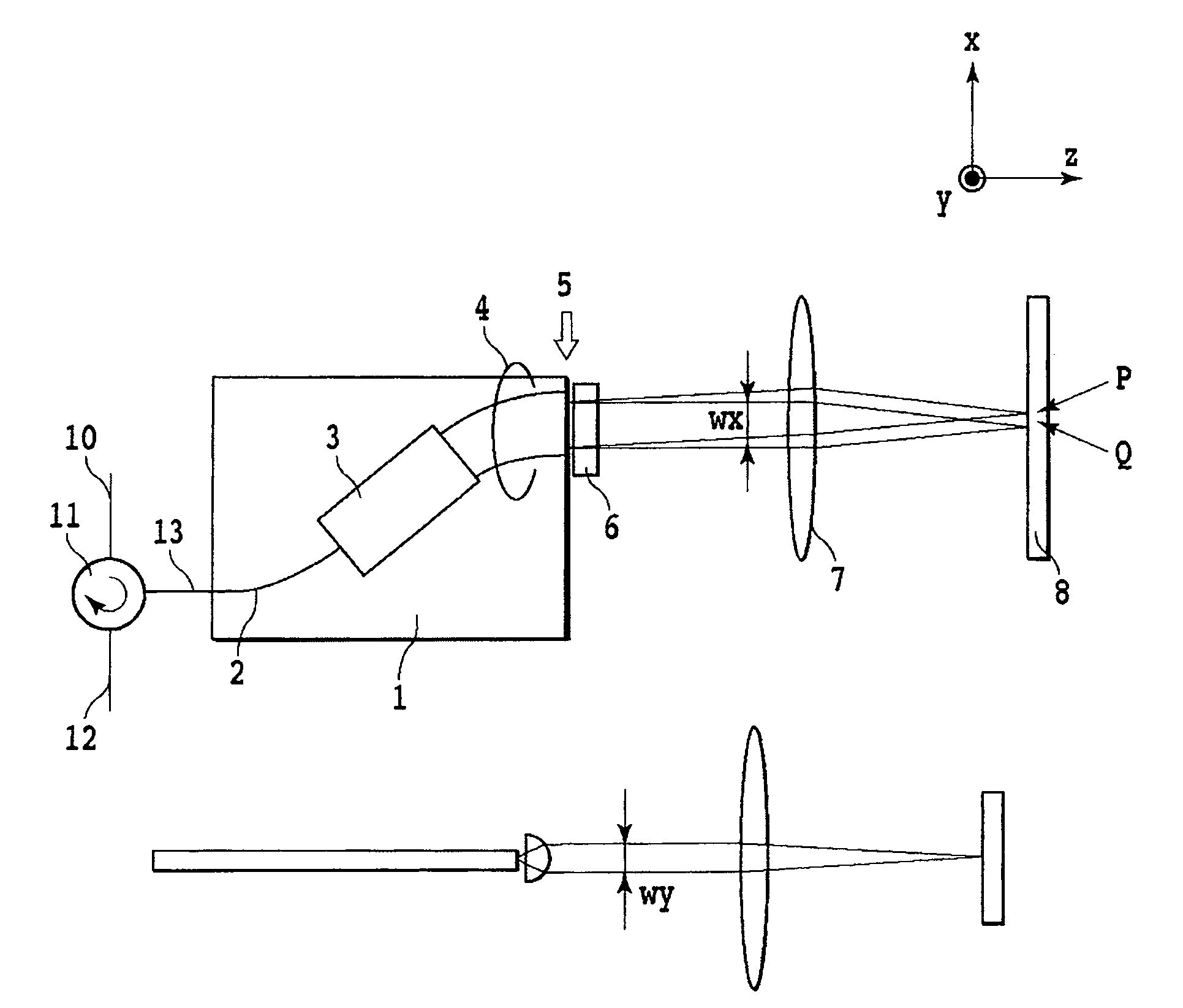
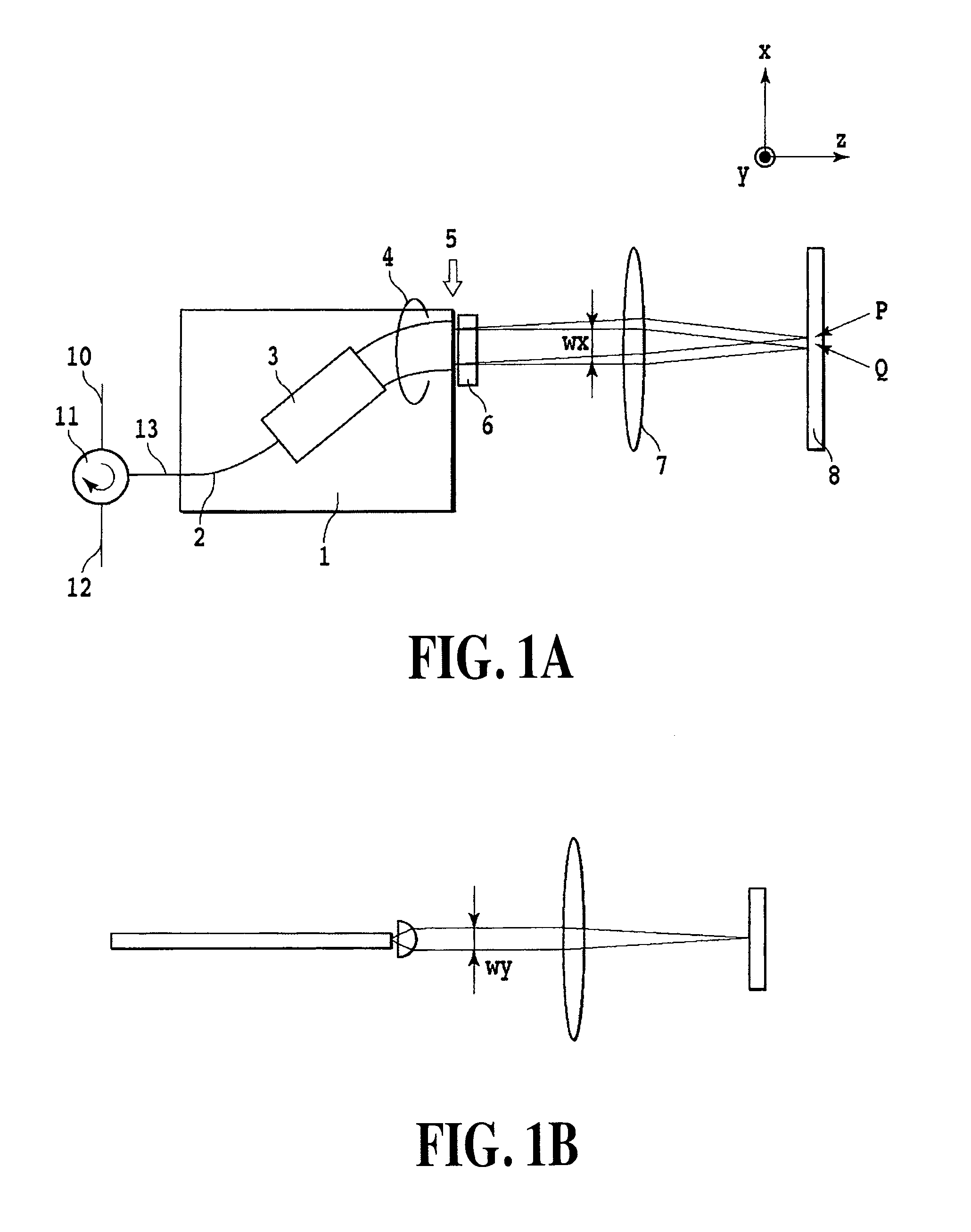
[0069]FIGS. 1A and 1B are views illustrating the configuration of a dispersion compensator according to a first embodiment of the present invention. FIG. 1A is a top view (an x-z plane) of an AWG substrate, while FIG. 1B is a side view (a y-z plane) thereof. The dispersion compensator according to the present invention is made up of a circulator 11 for input / output of optical signals; and a free space optical system which includes an arrayed-waveguide grating 1 (hereinafter referred to as AWG), a cylindrical lens 6, a focusing lens 7, and a spatial light modulator 8. The dispersion compensator includes a so-called reflective optical signal processing system in which an input optical signal is reflected upon the spatial light modulator 8 and the optical signal is delivered via the same AWG 1. The spatial light modulator implements the dispersion compensator unique to the present invention.

[0070]In more detail, an optical signal coming through an input fiber 10 is incident upon an inp...

second embodiment

[0087]FIG. 6 is a view illustrating the configuration of the dispersion compensator according to a second embodiment of the present invention. This dispersion compensator is also of the same reflection type as that of the first embodiment, but different therefrom in that a bulk-type diffraction grating 15 is further included, and an optical signal is spatially dispersed using a bulk-type diffraction grating. Furthermore, a key feature of this embodiment lies in that when viewed through an optical path, the AWG and the dispersion plane of the bulk-type diffraction grating are orthogonal to each other. Now, the differences between the second and first embodiments will be described in detail below.

[0088]As with the first embodiment, an optical signal supplied through the input fiber 10 is incident upon the input waveguide 2 of the AWG 1 via the circulator 11 and the coupling fiber 13. The optical signal incident upon the input waveguide 2 propagates to the arrayed waveguide 4 via the s...

third embodiment

[0106]Now, description will be made for a dispersion compensator, according to an embodiment with pixels disposed in a different manner, which has a combination of the arrayed-waveguide grating 1 and the bulk-type diffraction grating 15 as with the second embodiment. In the second embodiment, as shown in Equation (5), the ellipse radius wv of a focusing spot in the direction of v was less than the pixel width wSLMv of the spatial light modulator. However, conversely, it is also possible to make the ellipse radius wv of the focusing spot in the direction of v greater than the pixel width wSLMv as shown in the following equation;

wSLMv<<wv  Equation (6).

[0107]FIG. 9 is a view illustrating the relationship between the focusing spot size and the pixel on the spatial light modulator of a dispersion compensator according to a third embodiment. In FIG. 9, pixels are configured such that the amount of shift dv of the focusing spot in the direction of v per one optical signal channel du...


PUM

PropertyMeasurementUnit
sizeaaaaaaaaaa
width wSLMaaaaaaaaaa

Abstract

Conventional dispersion compensators were not sufficient to satisfy a demand to set a different dispersion value for each WDM wavelength in a ring-mesh type network that utilizes wavelength selective switches or the like. The devices were insufficiently reduced in size and power consumption and used with difficulty to change dispersion characteristics for each wavelength flexibly in a simple manner. A dispersion compensator of the present invention uses general-purpose optical components including a spatial light modulator for providing discrete phases to set appropriately the relationship between the focusing beam radius and the spatial light modulator pixel, thereby providing various dispersion compensation characteristics. Attention is focused on the correspondence between multiple pixels on the spatial light modulator providing discrete phases and a communication channel band, thereby allowing for changing the flexible dispersion characteristics and realizing the setting of an independent dispersion value for each WDM wavelength.

Description

TECHNICAL FIELD[0001]The present invention relates to a dispersion compensator to be used in optical fiber communications.BACKGROUND ART[0002]With the explosive growth of the Internet as a backdrop, wavelength division multiplexing (WDM) communication is now being transferred from the conventional point-to-point type system to the ring-mesh type system. This is because the ring-mesh type system can use a transparent wavelength selective switch or the like which processes an optical signal without changing its optical state, thereby flexibly handling variations in demand for communications between nodes. However, when optical paths are changed over in the ring-mesh type network, the dispersion values of the paths also change dynamically. This in turn requires adaptability to dispersion compensation in the optical communication path. Conventional dispersion compensators were predominantly of a type that collectively compensate a plurality of channels. However, in the ring-mesh type ne...

Claims


Application Information

Patent Timeline
Patent Type & Authority Patents(United States)
IPC IPC(8): H04J14/02H04B10/18G02B26/06G02F1/01H04B10/2507H04B10/2525
CPCG02B6/12021G02B6/12033G02B6/29394G02F2203/12G02F2203/18
Inventor SUZUKI, KENYASENO, KAZUNORIOOBA, NAOKIMINO, SHINJIISHII, MOTOHAYA
Owner NIPPON TELEGRAPH & TELEPHONE CORP
Why Eureka
Try Eureka