
Method for purification of exhaust gas from internal combustion engine

a technology for internal combustion engines and exhaust gas, which is applied in the direction of physical/chemical process catalysts, separation processes, metal/metal-oxide/metal-hydroxide catalysts, etc. it can solve the problems of adverse effect on running performance or environment, and achieve the reduction of production costs, reducing the limitation of installment places, and reducing the effect of hydrocarbon poisoning

Active Publication Date: 2013-04-16
UMICORE SHOKUBAI USA +1
View PDF34 Cites 4 Cited by
  • Summary
  • Abstract
  • Description
  • Claims
  • Application Information

AI Technical Summary

Benefits of technology

This approach enables efficient and stable regeneration of diesel particulate filters by enhancing combustion characteristics and temperature increase, reducing hydrocarbon poisoning, and maintaining filter performance over a long period.

Problems solved by technology

However, such control lengthens regeneration time, resulting in adverse effect on running performance or environment.
Accordingly, more rapid temperature increasing performance has been required, and in order to attain this, it is a problem to enhance combustion characteristics and temperature increasing performances for high concentration hydrocarbon at low temperature.

Method used


Image

  • Method for purification of exhaust gas from internal combustion engine
  • Method for purification of exhaust gas from internal combustion engine

Examples


example 1

[0066]Water was added to a dinitroamine platinum aqueous solution in an amount equivalent to 2 g of platinum, a magnesium acetate tetrahydrate in an amount equivalent to 0.6 g of magnesium, a palladium nitrate aqueous solution in an amount equivalent to 0.5 g of palladium, and 120 g of alumina (γ-Al2O3, with a BET specific surface area of 200 m2 / g, and an average primary particle diameter of 6 μm), to be subjected to wet grinding in a ball mill. Similar operation was repeated several times to prepare 1500 g in total of aqueous slurry. This slurry was wash-coated onto 1 L of monolith honeycomb carrier made of cordierite, having 400 cells per 1 square inch of cross-sectional area, and subjected to drying at 120° C. for 8 hours, and then calcining at 500° C. for 1 hour to obtain a catalyst A. Supported amount of each component of the resulting catalyst A, per 1-L of monolith carrier, was 2 g of platinum, 0.5 g of palladium and 0.6 g of magnesium.

example 2

[0067]A catalyst B was obtained by a similar method as in Example 1, except that instead of magnesium acetate tetrahydrate in an amount equivalent to 0.6 g of magnesium, magnesium acetate tetrahydrate in an amount equivalent to 1.2 g of magnesium was used.

example 3

[0068]A catalyst C was obtained by a similar method as in Example 1, except that instead of magnesium acetate tetrahydrate in an amount equivalent to 0.6 g of magnesium, magnesium acetate tetrahydrate in an amount equivalent to 6 g of magnesium was used.


PUM

PropertyMeasurementUnit
temperatureaaaaaaaaaa

Abstract

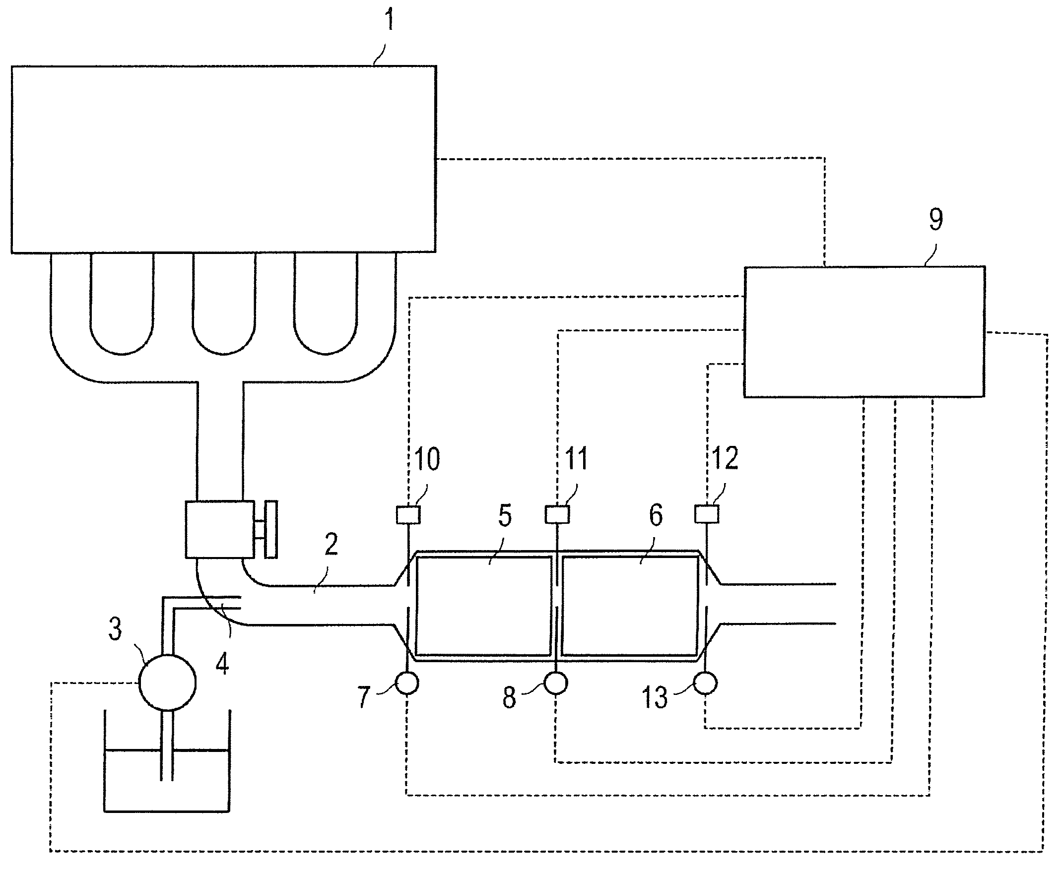
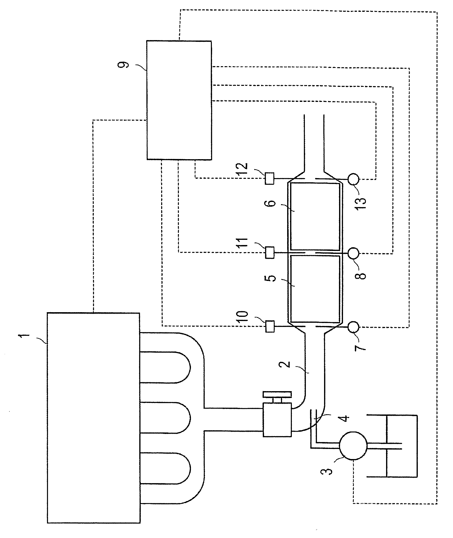
Temperature range enabling combustion of high concentration hydrocarbon is enlarged, or high temperature gas is rapidly supplied to a latter part catalyst. Provided is a method for purification of exhaust gas from an internal combustion engine, by using a catalyst for increasing temperature of exhaust gas from an internal combustion engine, wherein hydrocarbon from 1,000 to 40,000 ppm by volume, as converted to methane, to the exhaust gas, is introduced at the upstream side of the catalyst for increasing temperature, along flow of the exhaust gas inside a passage of exhaust gas from the internal combustion engine.

Description

TECHNICAL FIELD[0001]The present invention relates to a method for purification of exhaust gas from an internal combustion engine, and in more detail the present invention relates to a purification method excellent in removing particulates and the like from exhaust gas from an internal combustion engine such as diesel engine.BACKGROUND ART[0002]In order to trap PM (a particulate material) such as black smoke or SOF, exhausted from an internal combustion engine such as diesel engine or the like, a diesel particulate filter is used, and accompanying with the use thereof, a problem is raised that PM is deposited inside the filter, resulting in increase in pressure loss.[0003]Accordingly, as countermeasure for PM deposition, the filter is conventionally regenerated by arranging a heating apparatus such as an electric heater at the filter, to combust and remove PM by heating (JP-B-2953409).[0004]However, such a regeneration method had a problem of increased consumption power and high run...

Claims


Application Information

Patent Timeline
Patent Type & Authority Patents(United States)
IPC IPC(8): F01N3/00
CPCF01N13/0097B01D53/9472B01J23/58F01N3/0253F01N3/0821F01N3/0842F01N3/106F01N11/00B01D53/9422B01D2251/208B01D2255/102B01D2255/2047B01J37/0246F01N2560/06F01N2560/08F01N2560/14Y02T10/47Y02T10/22B01D53/945Y02T10/12Y02T10/40B01D53/94F01N3/02F01N3/20F01N3/24
Inventor IKEDA, MASANORIKATO, NAOHIRO
Owner UMICORE SHOKUBAI USA
Learn More