
Sagnac loop mirror based laser cavity on silicon photonics platform

a laser cavity and photonics technology, applied in the field of optical cavities, can solve the problem of prohibitively difficult electric pumping of silicon lasers

Active Publication Date: 2015-06-16
NOKIA SOLUTIONS & NETWORKS OY
View PDF5 Cites 14 Cited by
  • Summary
  • Abstract
  • Description
  • Claims
  • Application Information

AI Technical Summary

Benefits of technology

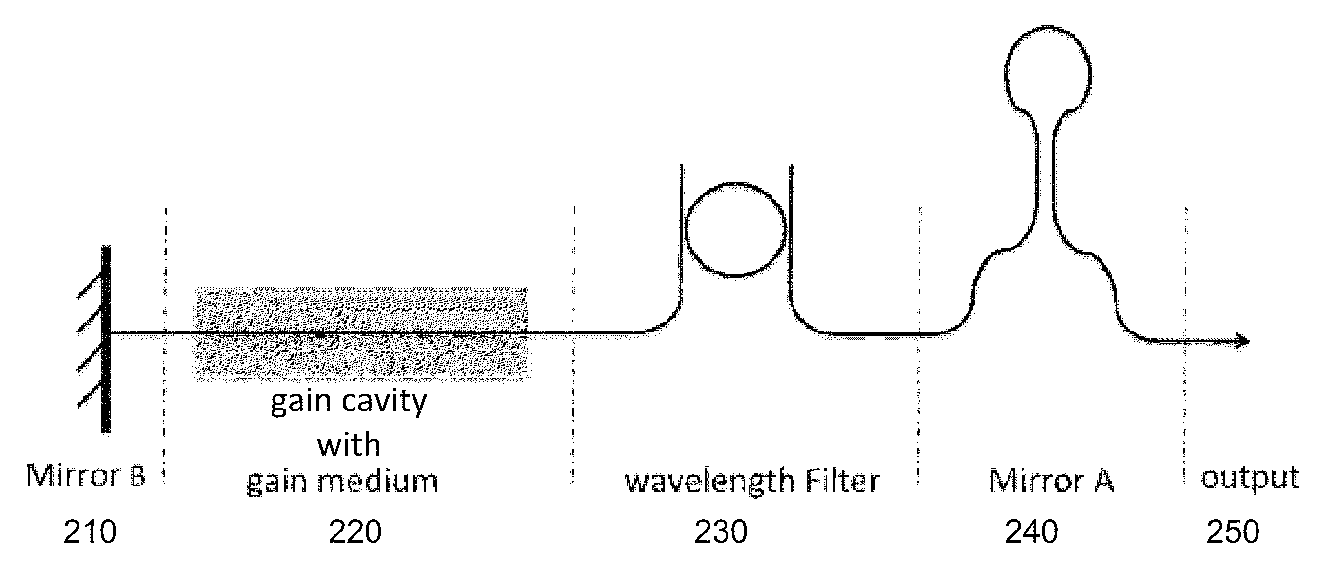
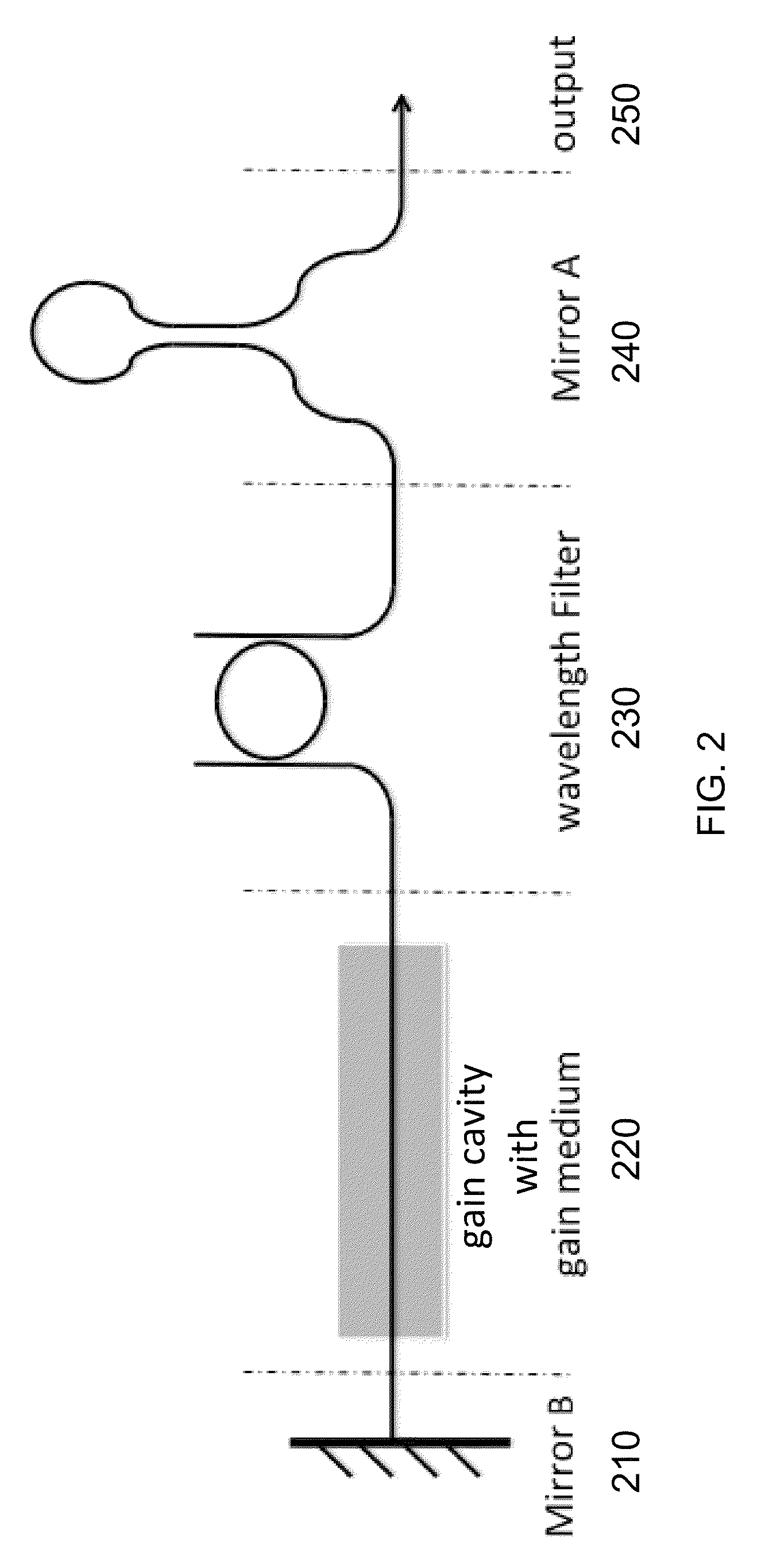
The invention is a device called an optical cavity which has several components. These components include a mirror, a filter, and a gain cavity. These components work together to produce an optical output beam with a specific optical wavelength. The invention has several advantages such as being able to operate without cooling or hermetic sealing. The output beam can have a narrow linewidth and be focused to a specific point. These technical effects make this invention useful for applications in telecommunications and other fields.

Problems solved by technology

Making an electrically pumped silicon laser is prohibitively difficult.

Method used


Image

  • Sagnac loop mirror based laser cavity on silicon photonics platform
  • Sagnac loop mirror based laser cavity on silicon photonics platform
  • Sagnac loop mirror based laser cavity on silicon photonics platform

Examples


Embodiment Construction

Acronyms

[0058]A list of acronyms and their usual meanings in the present document (unless otherwise explicitly stated to denote a different thing) are presented below.[0059]AMR Adabatic Micro-Ring[0060]APD Avalanche Photodetector[0061]ARM Anti-Reflection Microstructure[0062]ASE Amplified Spontaneous Emission[0063]BER Bit Error Rate[0064]BOX Buried Oxide[0065]CMOS Complementary Metal-Oxide-Semiconductor[0066]CMP Chemical-Mechanical Planarization[0067]DBR Distributed Bragg Reflector[0068]DC (optics) Directional Coupler[0069]DC (electronics) Direct Current[0070]DCA Digital Communication Analyzer[0071]DRC Design Rule Checking[0072]DUT Device Under Test[0073]ECL External Cavity Laser[0074]FDTD Finite Difference Time Domain[0075]FOM Figure of Merit[0076]FSR Free Spectral Range[0077]FWHM Full Width at Half Maximum[0078]GaAs Gallium Arsenide[0079]InP Indium Phosphide[0080]LiNO3 Lithium Niobate[0081]LIV Light intensity(L)-Current(I)-Voltage(V)[0082]MFD Mode Field Diameter[0083]MPW Multi Proj...


PUM


Abstract

We have demonstrated a novel Sagnac loop and micro-ring based laser cavity which is simple and reliable, with accurately controlled reflectivity and negligible excess loss. The resonant wavelength of a 2 μm radius micro-ring is shown to be lithographically controlled to a standard deviation of 3.6 nm. Both C- and O-Band lasers based on Sagnac loop mirror and micro-ring cavity have been demonstrated. The lasers are shown to be able to be modulated at 40 Gb / s.

Description

CROSS-REFERENCE TO RELATED APPLICATIONS[0001]This application claims priority to and the benefit of U.S. provisional patent application Ser. No. 61 / 906,529, filed Nov. 20, 2013, which application is incorporated herein by reference in its entirety.STATEMENT REGARDING FEDERALLY FUNDED RESEARCH OR DEVELOPMENT[0002]This invention was made with government support under FA-9550-10-1-0439 awarded by Air Force Office of Scientific Research (AFOSR). The government has certain rights in the invention.FIELD OF THE INVENTION[0003]The invention relates to optical cavities in general and particularly to an optical cavity that can be used with lasers.BACKGROUND OF THE INVENTION[0004]Semiconductor lasers and optical amplifiers are preferred in transceivers because they are efficiently electrically pumped and the die size is small. Lasing is a radiative recombination process in semiconductors, where an electron in the conduction recombines with a hole in the valance band and a photon is emitted. Th...

Claims


Application Information

Patent Timeline
Patent Type & Authority Patents(United States)
IPC IPC(8): H01S3/08H01S5/40H01S3/081H01S5/14H01S3/00
CPCH01S3/081H01S5/146H01S5/141H01S5/14H01S5/4062H01S3/005H01S3/0078H01S5/1032H01S5/142H01S5/3412G02B6/1223G02B6/12007H01S5/1014
Inventor ZHANG, YIYANG, SHUYUHOCHBERG, MICHAEL J.BAEHR-JONES, THOMAS
Owner NOKIA SOLUTIONS & NETWORKS OY
Learn More