System and method for integrated waste storage

a waste storage and waste technology, applied in the field of alternative energy, fuels, petrochemicals, can solve the problems of increasing transportation costs for moving fuel feed stocks for energy and petrochemical production, increasing the amount of pollutants to be generated in the gas given off, and increasing the cost of fuel supply

Active Publication Date: 2015-12-22
REPOWER IP LLC
View PDF101 Cites 21 Cited by
  • Summary
  • Abstract
  • Description
  • Claims
  • Application Information

AI Technical Summary

Benefits of technology

[0139]It is thought that the integrated waste storage system and method of the present invention and many of its attendant advantages will be understood from the foregoing description and it will be apparent that various changes may be made in the form, construction arrangement of parts thereof without departing from the spirit and scope of the invention or sacrificing all of its material advantages, the form hereinbefore described being merely a preferred or exemplary embodiment thereof.

Problems solved by technology

Sources of fuel useful for heating, transportation, and the production of petrochemicals are becoming increasingly scarce and therefore more costly.
Additionally, due to the ever increasing costs of fossil fuels, transportation costs for moving fuel feed stocks for production of energy and petrochemicals is rapidly escalating.
However, the brute force nature of complete combustion of fuel causes significant amounts of pollutants to be generated in the gas given off during combustion.
Fine particle pollution from U.S. power plants cuts short the lives of over 30,000 people each year.
The primary disadvantage of updraft gasification is that the synthesis gas contains 10-20% tar by weight, requiring extensive syngas cleanup before engine, turbine or synthesis applications.
The disadvantages of downdraft gasification are: requires feed drying to a low moisture content (<20%).
The disadvantages of bubbling fluidized-bed gasification are: lower gas-solid contact efficiency due to formation of bubbles, and increased attrition and dust entrainment rates large bubble size may result in gas bypass through the bed.
The circulating fluidized bed gasifiers operate at gas velocities higher than the so-called transport velocity, resulting in significant entrainment of the particles in the gas stream.
The disadvantages of circulating fluidized-bed gasification are: temperature gradients occur in the direction of solid flow; smaller particles are required; high velocities may result in equipment erosion; and heat exchange is less efficient than bubbling fluidized-bed.
Since some of these fuel sources are becoming increasingly more expensive, energy and petrochemical suppliers are seeking alternative fuel feed stocks.
One potential source of a large amount of feed stock for gasification is waste.
One of the most significant threats facing the environment today is the release of greenhouse gases (GHGs) into the atmosphere.
GHGs such as carbon dioxide, methane, nitrous oxide, water vapor, carbon monoxide, nitrogen oxide, nitrogen dioxide, and ozone, absorb heat from incoming solar radiation but do not allow long-wave radiation to reflect back into space.
However, only few have provided economically affordable improvements or effective solutions to the solid waste problems.
Of course, incineration, although reducing the volume of wastes disposed of in landfills, creates a large GHG emission and thereby the carbon foot print of the disposed of product, now waste, is not decreased.
Most waste energy recovery projects cost the municipalities more than the original landfills they replace, and do not represent substantial environmental improvements.
If the replaced material is biotic (material derived from living organisms), it is not always possible to obtain reductions of emissions.

Method used


Image

  • System and method for integrated waste storage
  • System and method for integrated waste storage
  • System and method for integrated waste storage

Examples


Embodiment Construction

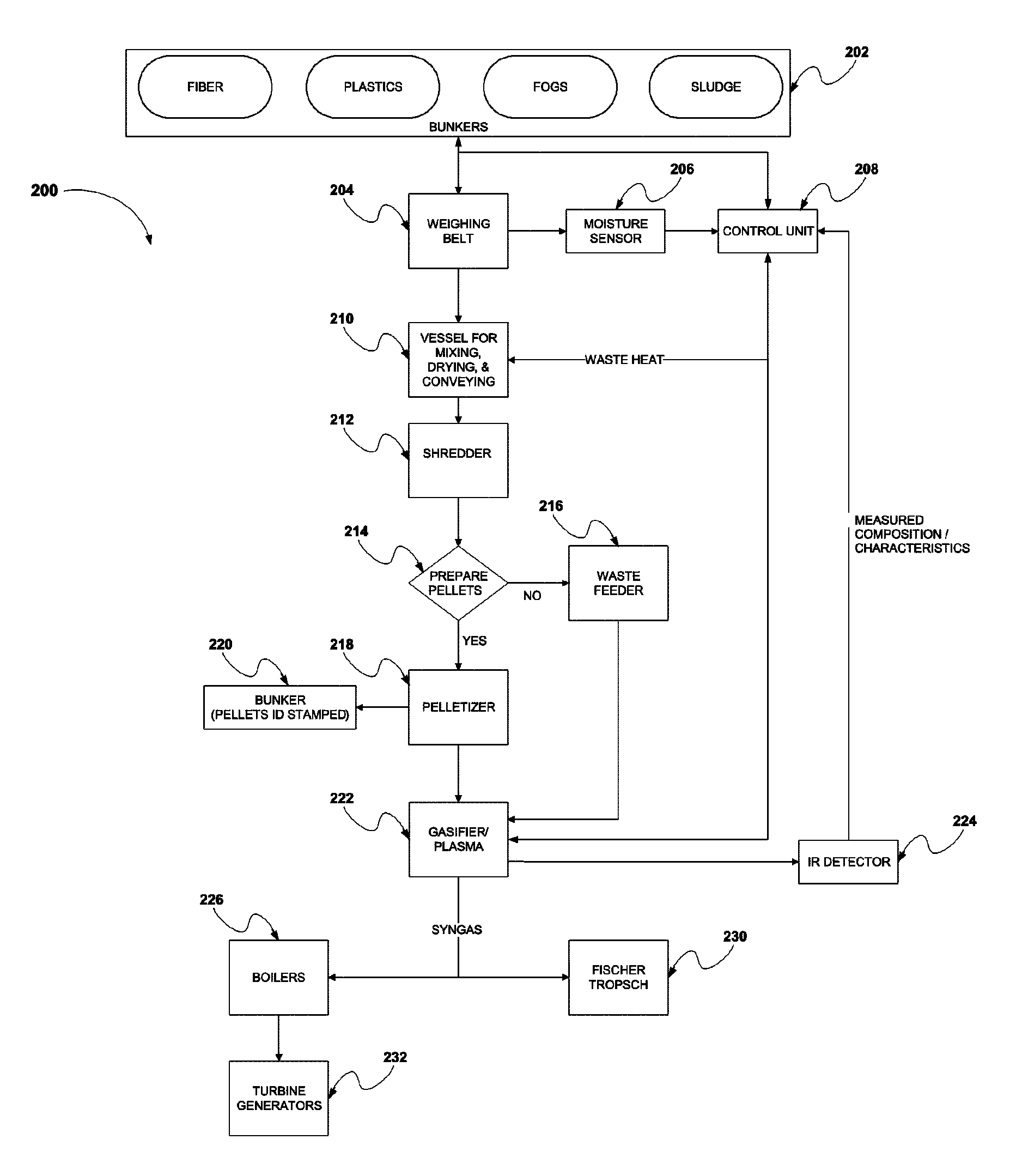
[0058]Gasification is a thermochemical process that generates a gaseous, fuel rich product. Regardless of how the gasifier is designed, two processes must take place in order to produce a useable fuel gas. In the first stage, pyrolysis releases the volatile components of the fuel at temperatures below 600° C. (1112° F.). The by-product of pyrolysis that is not vaporized, typically called char, consists mainly of fixed carbon and ash. In the second gasification stage, the carbon remaining after pyrolysis is either reacted with steam, hydrogen, air, or pure oxygen. Gasification with air results in a nitrogen-rich, low energy content fuel gas. Gasification with pure oxygen results in a higher quality mixture of carbon monoxide and hydrogen and virtually no nitrogen. Gasification with steam is more commonly called “reforming” and results in a hydrogen and carbon dioxide rich “synthesis” gas (syngas). Typically, the exothermic reaction between carbon and oxygen provides the heat energy r...


PUM

PropertyMeasurementUnit
temperaturesaaaaaaaaaa
temperatureaaaaaaaaaa

Abstract

The present invention provides integrated bunker storage systems for waste streams based on the composition and characteristics of waste streams. In particular, the present invention provides a process for generating individual waste streams based on a set of material characteristics. According to the system and method of the present invention, individual waste streams from wastes stored in bunkers are mixed in a given feed ratio to generate a feed stock that will produce a desired output from a chemical conversion process, e.g., gasification. Optionally, composition data regarding the feed stock can be certified to a third party.

Description

CROSS REFERENCE TO RELATED APPLICATIONS[0001]This application claims the benefit under 35 U.S.C. §119(e) of U.S. Provisional Patent Application No. 61 / 075,988, filed on Jun. 26, 2008, entitled System And Method For Integrated Waste Storage, which is herein incorporated by reference in its entirety.FIELD OF THE INVENTION[0002]The present invention generally relates to alternative energy, fuels, and petrochemicals. More particularly, the present invention is concerned with the recovery of energy and / or raw materials from waste materials stored in an integrated bunker storage system, and provides a process for generating feed stock from the waste streams for optimum conversion to energy, fuel, or petrochemicals.BACKGROUND OF THE INVENTION[0003]Sources of fuel useful for heating, transportation, and the production of petrochemicals are becoming increasingly scarce and therefore more costly. Industries such as those producing energy and petrochemicals are actively searching for cost effe...

Claims


Application Information

Patent Timeline
Patent Type & Authority Patents(United States)
IPC IPC(8): C22B7/00C22B1/24B29B17/02B29K23/00B29K67/00
CPCC22B7/005B29B17/02C22B1/24Y02W30/622B29K2067/00Y02W30/54B29K2023/065Y02E20/18Y02P10/20Y02W30/62C10J3/72C10J2300/0946Y02W30/50
Inventor BOHLIG, JAMES W.CASELLA, DOUGLAS R.
Owner REPOWER IP LLC
Why Eureka
Try Eureka