Fabrication of a vascular system using sacrificial structures

a technology of vascular system and sacrificial structure, which is applied in the field of fabrication of vascular system using sacrificial structure, can solve the problems of physiologic derangement, death, and billions of dollars of outlays, and achieves the effects of high customization, easy fabrication, and scalable and inexpensiv

Active Publication Date: 2016-01-26
CORNELL UNIVERSITY
View PDF19 Cites 9 Cited by
  • Summary
  • Abstract
  • Description
  • Claims
  • Application Information

AI Technical Summary

Benefits of technology

[0025]A key advantage of the present invention is the ability to use fibers to make highly branched, larger in scale, two dimensional or three dimensional vascularized constructs. Individual fibers used in the present invention can be fused during the fabrication process to each other and / or to larger diameter tubes. This enables branching and elongation of the channel network, thus enabling fabrication of larger vascularized constructs which are scalable in all three dimensions. Furthermore, the channels can be designed and fabricated such that they are confluent with a feeding “artery” (inlet) and “draining” vein (outlet), both greater than or equal to 500 μm in diameter. These larger vessels can act as the vascular pedicle, or leash, for the tissue implants in which the vascular network preforms (VNPs) can be anastomosed, or connected, to the host vasculature using standard microsurgical techniques.
[0026]Techniques relying upon 3D printing for fabricating constructs with vascular networks are available but are prohibitively expensive. The time and expense required to make artificial tissue constructs that have clinically useful sizes or industrially useful amounts would render 3D printing prohibitively expensive. The methods used in this invention are scalable and inexpensive. Also, the shape of the vascularized network preform and the embedded vascular network is highly customizable. For example, the millimeter-sized channels could be placed in a predetermined pattern or shape in order to reproduce the macroscale vascular layout of the tissue to be replaced. The elongate fibers could be combed or exposed to mechanical stretching to align or orient the fibers.
[0027]It is the unique capability to scale up the constructs beyond several millimeters in size, the relative ease of fabrication and highly customizable vascularity of the preform which makes the present invention novel.

Problems solved by technology

Acute and chronic wounds are a significant burden to the healthcare system affecting millions of patients nationally and resulting in billions of dollars of outlays.
Every year several million people suffer irreversible damage or loss of one or more tissue or organ systems, resulting in disfigurement, loss of function, physiologic derangement, and death.
Despite the numerous benefits associated with tissue transfer, there are certainly drawbacks associated with these complex reconstructive procedures.
Harvesting the donor tissue is a complicated process and the resultant donor sites are often painful and carry substantial morbidity, especially in the diabetic population.
Patients who are elderly or carry other co-morbidities such as cardiopulmonary or renal disease are especially at risk for significant peri-operative complications because of the long anesthesia times, notable blood loss, and large fluid shifts.
However, because of the slow pace of vascular ingrowth, tissue engineers are constrained to designing constructs no thicker than a few millimeters, the limit of diffusion of nutrients from a vascular to a non-vascular area (Androjna et al., Tissue Engineering Part A 14:559-569 (2008)).
Diffusion of nutrients is highly limited and, therefore, restricts the size and thickness of artificial tissue implants.
Cells distant from a vascular area are prone to ischemic death because of a paucity of oxygen and nutrients required for cellular metabolism.
The creation of such vascularized constructs is currently beyond the capabilities of any contemporary tissue engineering approach.
Unfortunately, despite tremendous advances in the understanding of vasculogenesis and angiogenesis, including the creation of capillary-like networks from cellular constituents, investigators have thus far been unable to achieve the goal of creating a confluent de novo microvascular and macrovascular network.
Furthermore, the vascular networks that have been constructed remain microscopic in scale, and have not yet been integrated into appropriate tissue engineering scaffolds.
In short, the organizational process underlying the development of tissues and organs thus far remains too complex to engineer from “the ground up.”
Unfortunately, this is a highly fallible approach since constructs containing cells further than several hundred microns from the surface (the limits of diffusion) are prone to ischemic cell death because of a paucity of oxygen and nutrients required for cellular metabolism.
This technological hurdle has significantly stunted the development of tissue engineered products that may be widely applied in the clinical arena.
Because of their initial avascularity, both of these constructs are prone to infection and can only be placed in healthy, well vascularized wound beds.
Although these data demonstrate a successful “proof of concept”, the utility of this approach is limited by the need for a donor animal to provide the tissue, which must then be chemically treated to remove all cellular constituents.
Furthermore, their constructs could not be custom designed by tissue type or shape, attributes that will likely be required when constructing any “replacement part”, other than the flat sheet they utilized as a bladder wall replacement.
To date, none of these techniques have met the necessary dual criteria of providing physiologic flow through 3D microchannel networks with a capability of being surgically integrated into the host macrovasculature.
Thus, comprehensive vascularization of tissue in vitro is a major challenge in fabrication of bioengineered tissue.
Creating a proper connection between the engineered tissue and the host vasculature when the tissue is implanted is the next major challenge.
However, three dimensional (3D) fluidic network fabrication is currently time-consuming and difficult, requiring either layer-by-layer assembly of two dimensional (2D) structures formed using standard microfabrication techniques (such as photolithography and imprint lithography) (Luo et al., Lab on a Chip 8:1688-1694 (2008); Chiu et al., Proc. Natl. Acad. Sci. U.S.A.

Method used


Image

  • Fabrication of a vascular system using sacrificial structures
  • Fabrication of a vascular system using sacrificial structures
  • Fabrication of a vascular system using sacrificial structures

Examples


example 1

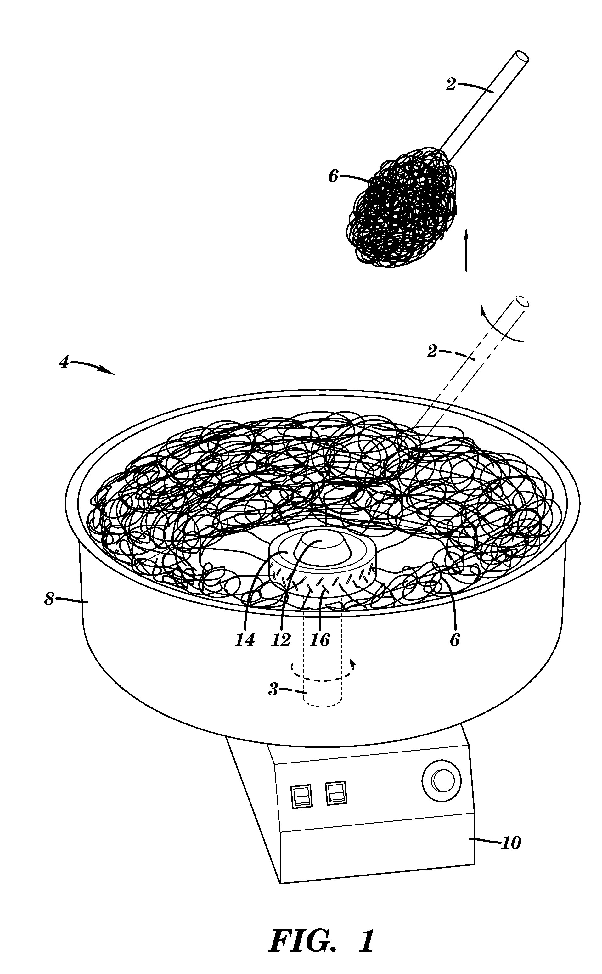
Sacrificial Microfiber Fabrication

[0104]To form the microchannels, melt-spun sugar fiber networks were produced using a modified cotton candy machine (The Helman Group, CCM-505). The cotton candy machine was modified to allow the user to exert more control over the process parameters. Store-bought granulated sugar was used in the machine. The heaters and the motor were each connected to variacs in order to control the extractor head temperature and rotational speed. The channel diameter and channel density may be controlled by varying the melt-spinning apparatus extractor head speed and temperature and by varying the fiber collection technique and subsequent handling, respectively (Bursac et al., Biochem. Biophys. Res. Commun., 361:847-853 (2007), which is hereby incorporated by reference in its entirety). The temperature of the extractor head was not varied from the default setting. Only 90V were supplied to the extractor head motor (as opposed to the line voltage), causing it to s...

example 2

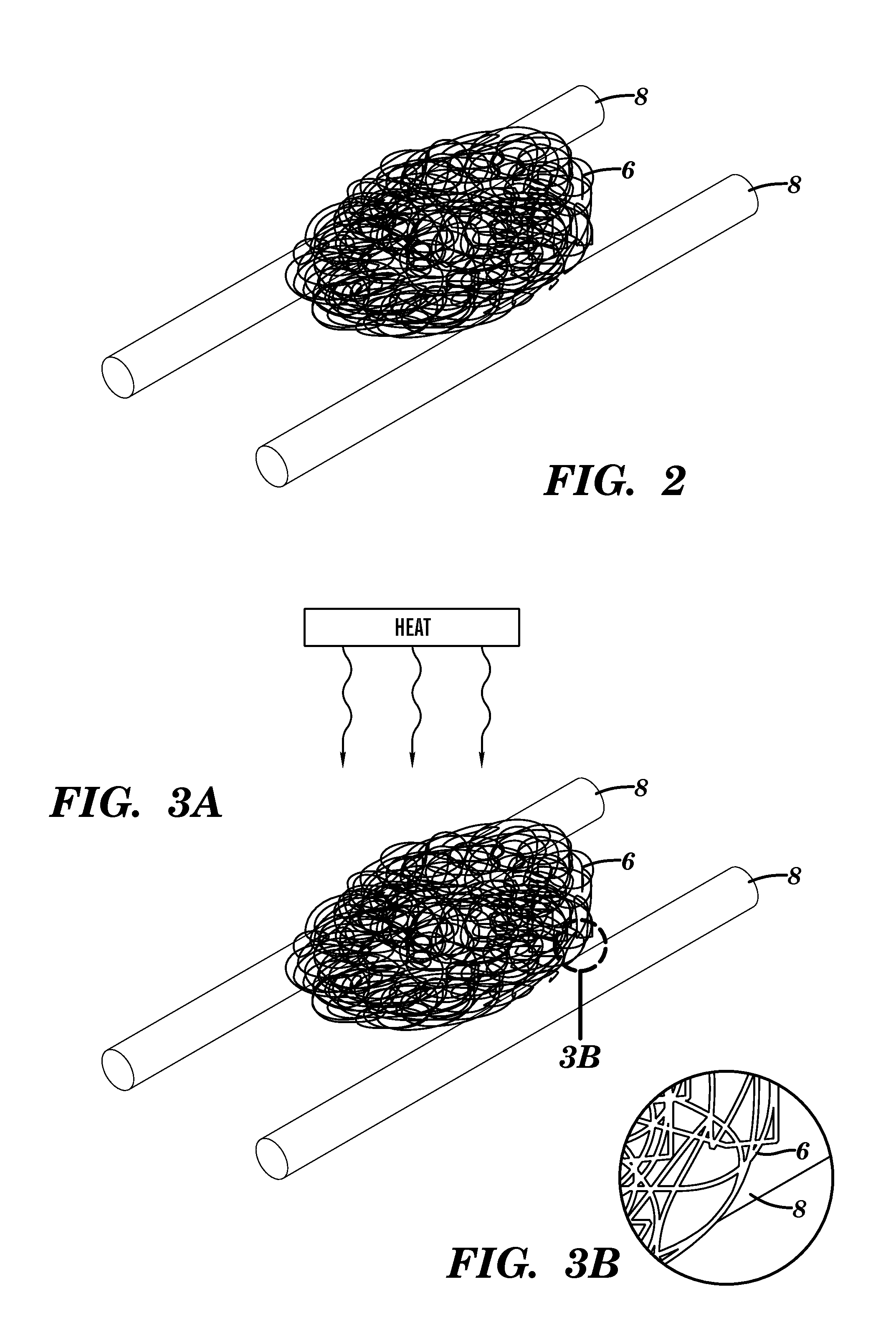
Sugar Stick Fabrication

[0105]Sticks of sugar were formed by pouring molten sugar onto aluminum foil. First, store-bought granulated sugar was melted in a beaker using a hot plate at approximately 190° C. The sugar was removed from the heat before it burned. The molten sugar was manually poured into thin lines on aluminum foil. The speed with which the molten sugar was dragged along the foil determined the sugar stick diameter. The molten sugar cooled quickly at room temperature, and could then be used as a sacrificial material to make macrochannels.

example 3

Assembly

[0106]The sugar sticks were embedded into the microfiber ball by hand. If the ambient humidity was not high enough to render the sugar sticks sticky, they were brought near running hot water to put them in a more humid environment. The sugar sticks were placed on the microfiber ball in the desired location, and the microfiber ball was then manually pressed into an appropriate size to fit in a Teflon mold.


PUM

PropertyMeasurementUnit
diameteraaaaaaaaaa
diameteraaaaaaaaaa
diameteraaaaaaaaaa

Abstract

The first aspect of the present invention is directed to a method of producing a vascular network preform (VNP). This method involves forming a network of elongate fibers and at least one elongate structure from a sacrificial material. The diameter of the elongate structure is greater than that of the elongate fibers. The network of elongate fibers is placed in contact with at least one elongate structure either following or during forming the network of elongate fibers or forming the at least one elongate structure. A matrix is applied around the network of elongate fibers, in contact with the at least one elongate structure. The network of elongate fibers and elongate structure, within the matrix is sacrificed to form a preform. The resulting preform contains a vascular network of fine diameter tubes in contact with at least one elongate passage having a diameter greater than that of the fine diameter tubes. The resulting solid preform and methods of using it are also disclosed.

Description

[0001]This application claims the benefit of U.S. Provisional Patent Application Ser. No. 61 / 081,898, filed Jul. 18, 2008.[0002]This invention was made with government support under grant numbers HRD-0630456, ECS-9876771, and DMR-0520404 by the National Science Foundation. The government has certain rights in this invention.FIELD OF THE INVENTION[0003]The present invention is directed to the fabrication of vascular systems using sacrificial structures.BACKGROUND OF THE INVENTION[0004]Acute and chronic wounds are a significant burden to the healthcare system affecting millions of patients nationally and resulting in billions of dollars of outlays. Every year several million people suffer irreversible damage or loss of one or more tissue or organ systems, resulting in disfigurement, loss of function, physiologic derangement, and death.[0005]A major leap forward in reconstructive surgery occurred in the 1960's and continued through the following decade with the discovery of “axial flap...

Claims


Application Information

Patent Timeline
Patent Type & Authority Patents(United States)
IPC IPC(8): A61F2/02B29C69/02B29C47/06A61L27/58A61L27/56A61L27/54A61L27/38A61M31/00
CPCA61L27/3808A61L27/54A61L27/56A61L27/58A61L2300/412A61L2300/414A61L2300/426A61L2300/602
Inventor BELLAN, LEON M.CRAIGHEAD, HAROLDSPECTOR, JASON A.
Owner CORNELL UNIVERSITY
Why Eureka
Try Eureka