Method of manufacturing material for rotary machine component, method of manufacturing rotary machine component, material for rotary machine component, rotary machine component, and centrifugal compressor

a technology of rotary machine components and manufacturing methods, which is applied in the direction of heat treatment equipment, liquid fuel engines, furnaces, etc., can solve the problems of material not being applied to components used in rotary machines, corrosion cracking, and low strength, so as to reduce residual stress of materials, reduce precipitation, and high toughness

Active Publication Date: 2016-03-29
MITSUBISHI HEAVY INDUSTIES COMPRESSOR CORP
View PDF14 Cites 0 Cited by
  • Summary
  • Abstract
  • Description
  • Claims
  • Application Information

AI Technical Summary

Benefits of technology

[0045]According to the method of manufacturing a rotary machine component having the related configuration, as above, after the material is formed by directly forging an ingot which is a duplex stainless steel material to a shape having dimensions similar to those of the rotary machine component, various working processes are performed thereon. Therefore, a rotary machine component in which the precipitation of an embrittled phase is suppressed and of which the toughness is excellent and which has a considerable thickness and a large diameter may be configured.
[0052]In addition, according to the rotary machine and the centrifugal compressor according to the aspects of the present invention, since the rotary machine component and the impeller obtained according to the manufacturing methods are used, corrosion or stress corrosion cracking that occurs due to corrosive components is suppressed, and thus the occurrence of cracking and the like during machine operation may be prevented.

Problems solved by technology

Therefore, in the impeller on which a high load is exerted during driving of the centrifugal compressor, corrosion occurs due to the corrosive components described above, and furthermore, there is a possibility of stress corrosion cracking occurring and resulting in fracture.
However, such materials have low strength and thus there is a problem in that the materials may not be applied to components used in a rotary machine such as an impeller of a centrifugal compressor.
However, such materials never have high corrosion resistance, and as above, there is a possibility of corrosion or stress corrosion cracking occurring due to the corrosive components.
However, even though such a material as described in Non Patent Document 1 is used, in a case where the proportion of corrosive components contained in a fluid increases, there is a possibility of corrosion or stress corrosion cracking occurring as above.
However, the precipitation-hardening Ni-base alloy as described above is expensive, and thus there is a problem in that manufacturing cost is increased.
However, in a case where the duplex stainless steel as described above is used for a rotary machine component such as the impeller, there are problems which may be described as follows.
Therefore, the toughness of the material is degraded, and there is a problem in that cracking is likely to occur in a manufacturing process of a corresponding component or during driving of a rotary machine such as the centrifugal compressor.
Therefore, as above, there is a problem in that cracking is likely to occur during the manufacturing process of a corresponding component or during driving of a rotary machine (see the graph of FIG. 9).
Therefore, hitherto, in the annealing process performed after the welding process or the machining process, a heat treatment is performed at a temperature of 300 to 400° C. which is insufficient to remove residual stress within a typical heat treatment time.

Method used


Image

  • Method of manufacturing material for rotary machine component, method of manufacturing rotary machine component, material for rotary machine component, rotary machine component, and centrifugal compressor
  • Method of manufacturing material for rotary machine component, method of manufacturing rotary machine component, material for rotary machine component, rotary machine component, and centrifugal compressor
  • Method of manufacturing material for rotary machine component, method of manufacturing rotary machine component, material for rotary machine component, rotary machine component, and centrifugal compressor

Examples


example 1

[0103]In Example 1, first, materials corresponding to SUS329J1, SUS329J3L, and SUS329J4L (all are made by Daido Steel Co., Ltd.) were prepared as duplex stainless steels, and a forging process was performed on each of the ingots thereof, thereby manufacturing round bar-like blooms having a diameter of 300 mm. In addition, the blooms were first heated to a temperature of 1050° C. as the solution treatment, and thereafter were water-cooled from 1050° C. to 700° C. at an average cooling rate of 31° C. / min that is equal to or greater than 30° C. / min, thereby manufacturing samples of the material for a rotary machine component.

example 2

[0104]In Example 2, first, as in Example 1, materials corresponding to SUS329J1, SUS329J3L, and SUS329J4L (all are made by Daido Steel Co., Ltd.) were prepared as duplex stainless steels, and a forging process was performed on each of the ingots thereof, thereby manufacturing samples of the material for a rotary machine component which are made of discoid materials having a thickness of 300 mm.

example 3

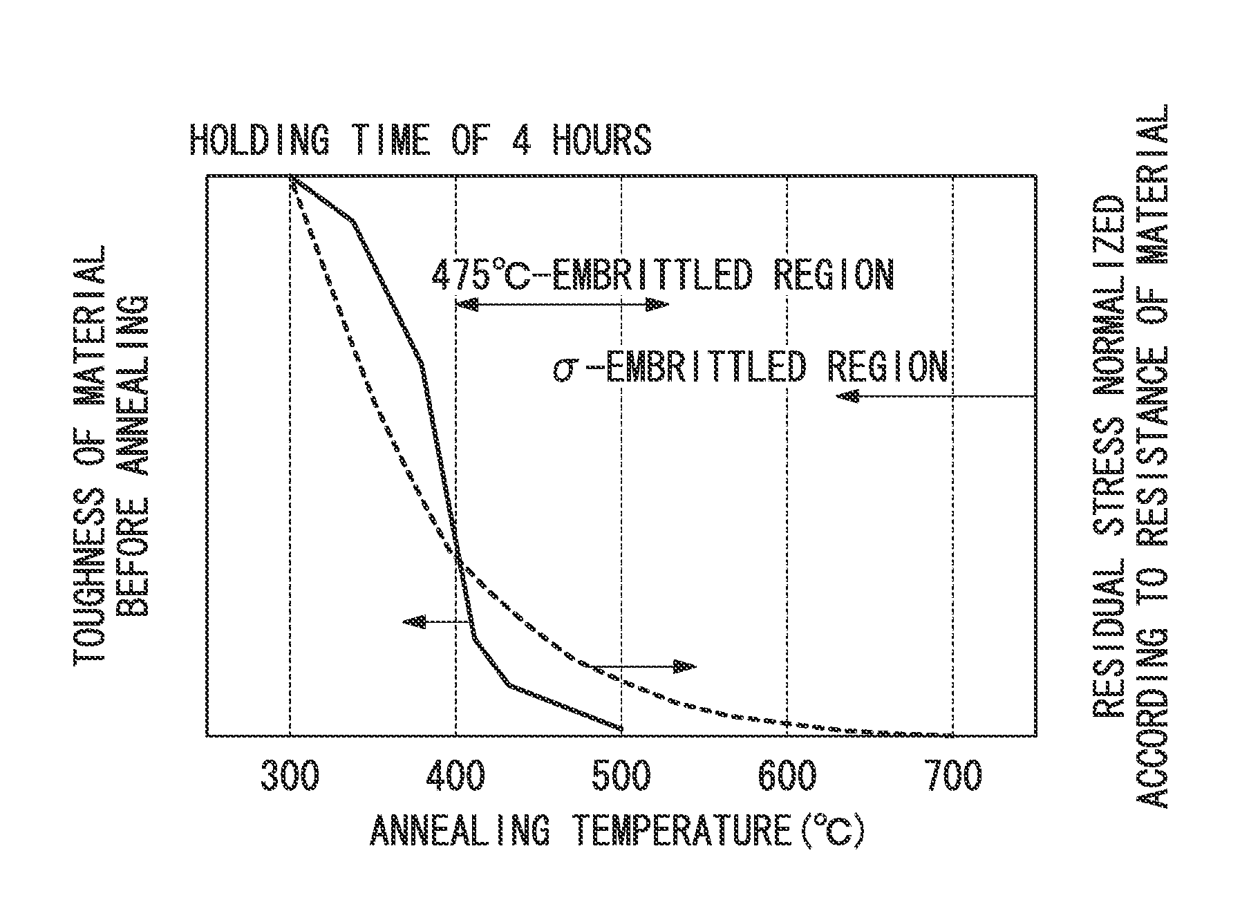
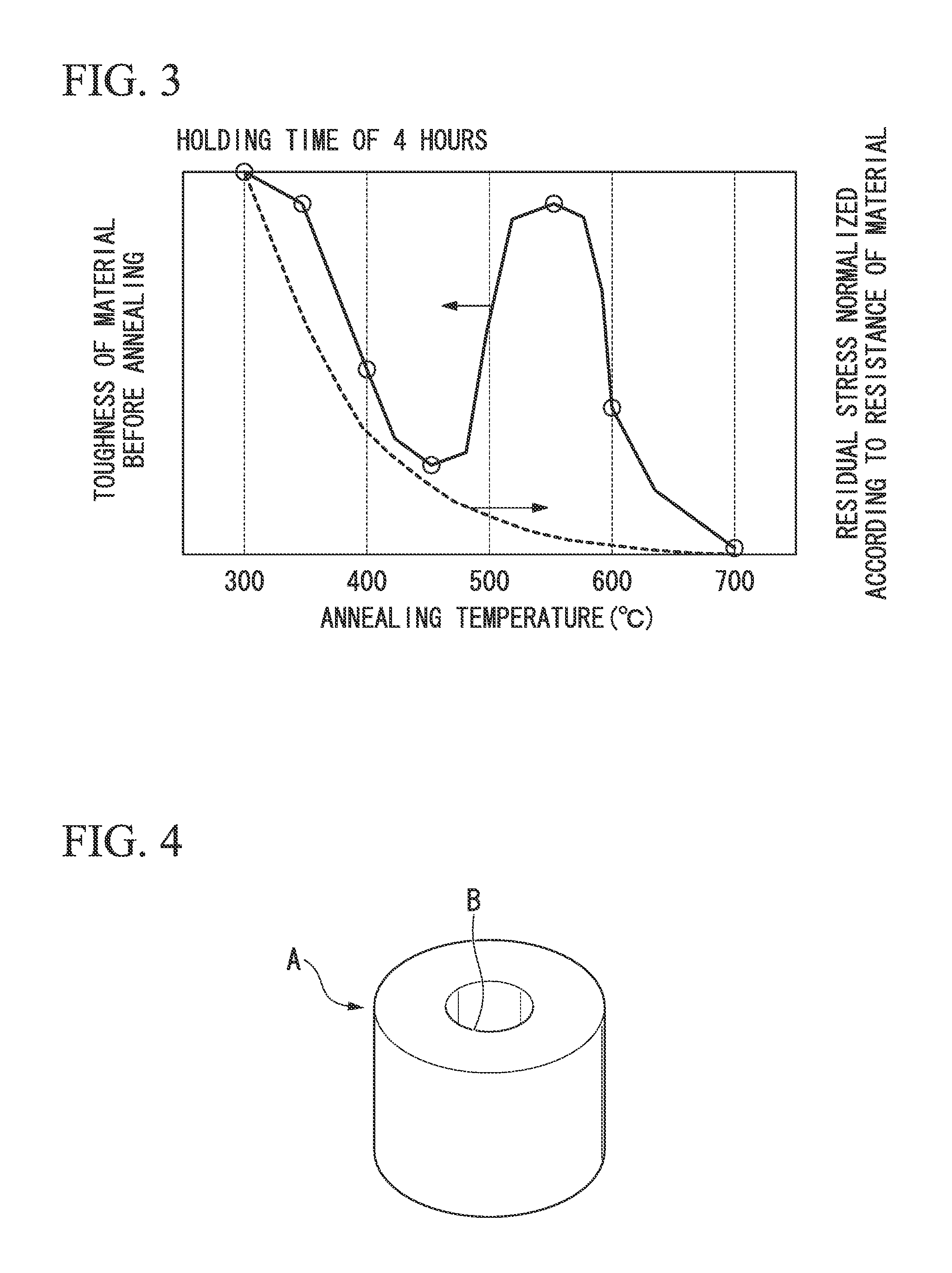
[0105]In Example 3, first, materials corresponding to SUS329J4L (made by Daido Steel Co., Ltd.) were prepared as duplex stainless steels, and a forging process was performed on each of the ingots thereof, thereby manufacturing round bar-like blooms having a diameter of 300 mm. In addition, as in Example 1, the blooms were first heated to a temperature of 1050° C. as the solution treatment, and thereafter were water-cooled from 1050° C. to 700° C. at an average cooling rate of 31° C. / min that is equal to or greater than 30° C. / min. Then, an annealing process for stress removal was performed by holding the blooms at a temperature of 550° C. for 4 hours, thereby manufacturing samples of the material for a rotary machine component.


PUM

PropertyMeasurementUnit
thicknessaaaaaaaaaa
temperatureaaaaaaaaaa

Abstract

A method of manufacturing a material for a rotary machine component, by performing at least a solution treatment on a material made of a duplex stainless steel, wherein, in the solution treatment, the material is heated to a temperature in a range of 950 to 1100° C. and is thereafter cooled to 700° C. at an average cooling rate of equal to or greater than 20° C. / min.

Description

BACKGROUND OF INVENTION[0001]1. Technical Field[0002]The present invention relates to a method of manufacturing a material for a rotary machine component, a method of manufacturing a rotary machine component, a material for a rotary machine component, a rotary machine component, and a centrifugal compressor.[0003]Priority is claimed on Japanese Patent Application No. 2010-111204, filed on May 13, 2010, the content of which is incorporated herein by reference.[0004]2. Background Art[0005]Hitherto, a rotary machine such as a centrifugal compressor is used for supplying gas to a turbine in a gas turbine, a process of injecting gas into the ground during extraction of crude oil from an oil field, and the like. Since a high load is exerted on the components used in such a rotary machine, a high-strength metal material is used as the material of a rotary machine component such as an impeller.[0006]On the other hand, in a centrifugal compressor used in an oil well environment or the like, ...

Claims


Application Information

Patent Timeline
Patent Type & Authority Patents(United States)
IPC IPC(8): C21D8/00C22C38/40F04D29/28C21D6/02C21D9/00C22C38/18C21D6/00C21D9/40C22C38/44C22C38/00F04D29/02C21D1/25C22C38/02C22C38/04C21D9/34
CPCC21D1/25C21D6/004C21D6/02F04D29/284C21D9/0068C21D9/40C22C38/00C22C38/001C22C38/02C22C38/04C22C38/44F04D29/023C21D9/34F05D2300/171F05D2260/95F05D2230/41
Inventor IWASAKI, SHUGOYAMADA, YOSHIKAZUTOKUYAMA, SHINICHIROOSAWA, TATSUYAYARIMIZU, SEIICHI
Owner MITSUBISHI HEAVY INDUSTIES COMPRESSOR CORP
Why Eureka
Try Eureka