Flexible metal laminate

a metal laminate and flexible technology, applied in the field of flexible metal laminates, can solve the problems of insignificant improvement, thermal plasticity, and the disclosure of copper foil laminates prepared into thin films, and achieve the effects of low dielectric constant, low moisture regain, and high elasticity

Active Publication Date: 2016-04-05
GUANGDONG SHENGYI SCI TECH
View PDF30 Cites 2 Cited by
  • Summary
  • Abstract
  • Description
  • Claims
  • Application Information

AI Technical Summary

Benefits of technology

[0080]According to the present invention, a flexible metal laminate which has a low dielectric constant and low moisture regain and can secure high elasticity and an optimized coefficient of thermal expansion can be provided.
[0081]Accordingly, the present invention provides a method of preparing a low dielectric constant polyimide having the characteristics of high heat resistance, chemical resistance, and dimensional stability the same as prior polyimide insulators, in addition to a low dielectric constant, as the solution to an increase of data loss caused by an increase of data transmission speed of recent electronic devices such as a laptop (notebook), a computer, a mobile phone, and so on, the thickening of a printed circuit board, and the narrowing of a circuit in a printed circuit board. Furthermore, the present invention provides a method of preparing a low dielectric constant copper foil laminate by using the low dielectric constant polyimide prepared by such method.
[0082]According to this, the printed circuit board can be prepared more thinly with matching impedance and it becomes possible to prepare portable electronic devices more thinly, and it can innovatively reduce the defect rate of PCB manufacturing companies and can contribute to a preparation cost reduction because the line width of printed circuit board can be wide.

Problems solved by technology

However, even if the LCP is applied thereto, the degree of improvement is insignificant because the dielectric constant of the LCP (Dk=2.9) is not significantly different from that of polyimide (Dk=3.2), and there is a problem that the compatibility with a PCB preparation process using the prior polyimide in a via hole process using a laser because the LCP has low thermal resistance to cause a problem in a soldering process and has thermal plasticity.
However, the patent relates not to an electronic product requiring a low dielectric constant but to a molded product, and it uses a polyimide having a high thermal expansion rate and a low glass transition temperature.
Further, it is required to form the polyimide resin into a thin film in order to use the same on a printed circuit board, but the above U.S. patent document does not disclose a copper foil laminate prepared into a thin film.
However, as disclosed in the above U.S. patent document, overall moisture regain of the same can be reduced because the fluoropolymer is plentiful in the outer layer of the insulator and moisture penetration and absorption are lowered because of a fluororesin at the outer surface, but there may be a problem that has not appeared in flexible copper foil laminates composed of the prior polyimide.
There is also a risk that the copper foil circuit may be exfoliated because too much fluororesin exists in the outer surface of the polyimide.

Method used


Image

  • Flexible metal laminate
  • Flexible metal laminate
  • Flexible metal laminate

Examples


preparation examples

Preparation of Polyamic Acid Solution

preparation example 1

Preparation of Polyamic Acid Solution (P1) Including Fluororesin

[0086]After filling nitrogen in a 1 L polyethylene (PE) bottle and adding 765 g of dimethylacetamide (DMAc), 219 g of polytetrafluoroethylene (PTFE) micro-powder (particle size: 0.1 to 2.0 μm), 10.95 g of a polyester-based polymer [acid value: 26 mg KOH / g, base equivalent: 1200] as a dispersing agent, and 765 g of beads having a diameter of 2 mm thereto, the resultant mixture was stirred in a high speed ball milling apparatus so as to disperse PTFE. After putting 80 g of the solution in which said PTFE was dispersed, 107 g of dimethylacetamide, 1.852 g of 3,4,3′,4′-biphenyltetracarboxylic dianhydride, 12.355 g of pyromellitic dianhydride, 5.453 g of 2,2′-dimethyl-4,4′-diaminobiphenyl, 12.340 g of 2,2′-bis(trifluoromethyl)-4,4′-diaminobiphenyl in a 500 mL round bottom flask, the mixture was stirred with a stirrer and reacted at 50° C. for 10 hours while streaming nitrogen therein so as to obtain a polyamic acid solution ...

preparation example 2

Preparation of Polyamic Acid Solution (P2) Including Fluororesin

[0087]After filling nitrogen in a 1 L polyethylene (PE) bottle and adding 765 g of dimethylacetamide (DMAc), 219 g of polytetrafluoroethylene (PTFE) micro-powder (particle size: 0.1 to 2.0 μm), 10.95 g of a polyester-based polymer [acid value: 26 mg KOH / g, base equivalent: 1200] as a dispersing agent, and 765 g of beads having a diameter of 2 mm thereto, the resultant mixture was stirred in a high speed ball milling apparatus so as to disperse PTFE. After putting 73 g of the solution in which said PTFE was dispersed, 115 g of dimethylacetamide, 11.609 g of pyromellitic dianhydride, 17.391 g of 2,2′-bis(trifluoromethyl)-4,4′-diaminobiphenyl in a 500 mL round bottom flask, the mixture was stirred with a stirrer and reacted at 50° C. for 10 hours while streaming nitrogen therein so as to obtain a polyamic acid solution (P2) having viscosity of about 100,000 cps.


PUM

PropertyMeasurementUnit
densityaaaaaaaaaa
diameteraaaaaaaaaa
thicknessaaaaaaaaaa

Abstract

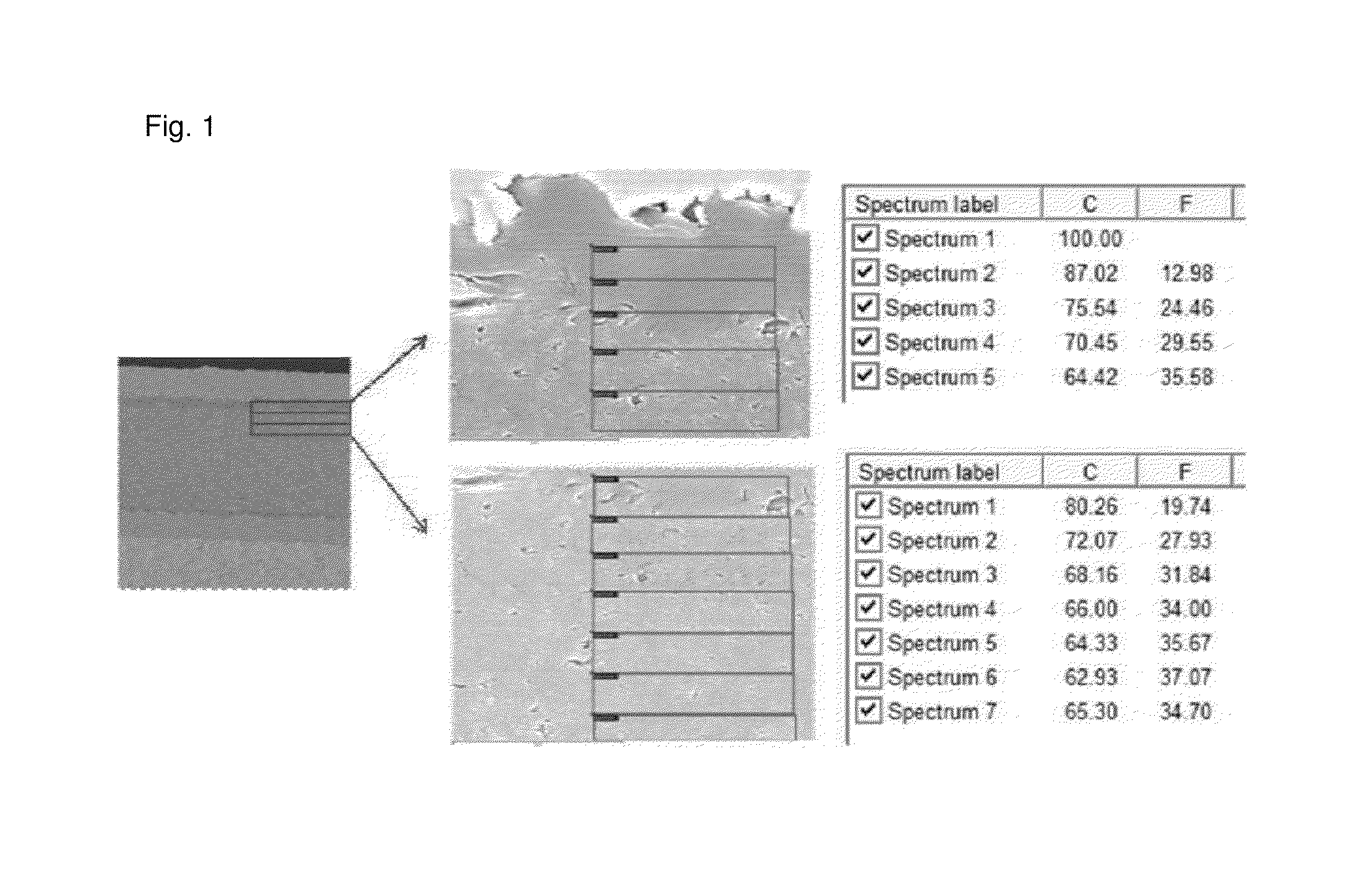
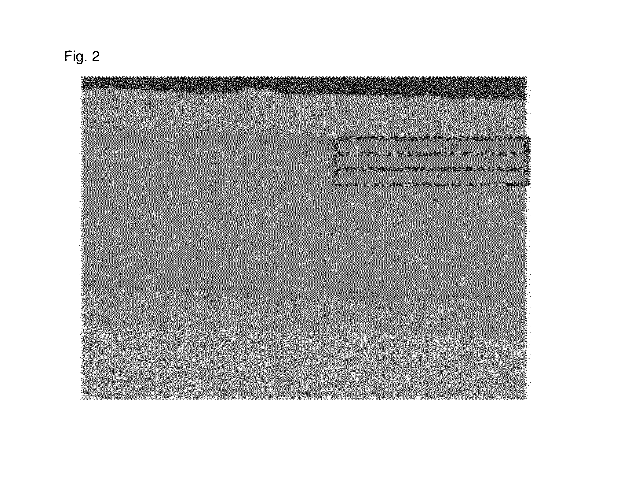
There is provided a flexible metal laminate including a polymer resin layer including a polyimide resin of a specific structure and a fluororesin, wherein the fluororesin is more distributed through the inside of the polymer resin layer than at the surface of the polymer resin layer.

Description

CROSS REFERENCE TO RELATED APPLICATION(S)[0001]This application is a 35 U.S.C. §371 National Phase Entry Application from International Application PCT / KR2013 / 006214, filed on Jul. 11, 2013, which claims under 35 U.S.C. §119 priority to and the benefit of Korean Patent Application No. 10-2012-0076501, filed Jul. 11, 2012, Korean Patent Application No. 10-2013-0081375, filed Jul. 11, 2013, the disclosures of which are incorporated herein by reference in their entireties.TECHNICAL FIELD[0002]The present invention relates to a flexible metal laminate, and specifically relates to a flexible metal laminate which has a low dielectric constant and low moisture regain and can secure high elasticity and an optimized coefficient of thermal expansion.BACKGROUND OF THE INVENTION[0003]Following the recent trend of miniaturization, high speed, and unification of various functions of electronic devices, the signal propagation velocity within electronic devices or the signal propagation velocity ou...

Claims


Application Information

Patent Timeline
Patent Type & Authority Patents(United States)
IPC IPC(8): H05K1/03H05K1/05H05K3/02
CPCH05K1/0353C09D127/18C08L79/08H05K1/0373H05K1/0393H05K3/022H05K2201/015H05K2201/0154Y10T428/24355Y10T428/25Y10T428/263Y10T428/264Y10T428/266Y10T428/3154Y10T428/31544B32B15/08C08G73/10H05K1/03
Inventor PARK, YOUNG SEOKPARK, SOON YONGJANG, SE MYUNG
Owner GUANGDONG SHENGYI SCI TECH
Why Eureka
Try Eureka