Electric field ferromagnetic resonance excitation method and magnetic function element employing same

a ferromagnetic resonance and excitation method technology, applied in the direction of magnetic bodies, instruments, heads with metal sheet cores, etc., can solve the problems of reassessing the roadmap, posing problems between adjacent elements, etc., and achieve the effect of efficient excitation of ferromagnetic resonance dynamics and low power

Active Publication Date: 2016-10-04
NAT INST OF ADVANCED IND SCI & TECH
View PDF30 Cites 14 Cited by
  • Summary
  • Abstract
  • Description
  • Claims
  • Application Information

AI Technical Summary

Benefits of technology

[0069]According to the present invention, merely by applying the magnetic field having the specific magnetic field application angle and magnetic field strength to the laminate structure and further by applying the electric field having the high-frequency component of the magnetic resonance frequency between the magnetic anisotropy control layer and the electrode layer, ferromagnetic resonance dynamics can be excited efficiently. The above-mentioned three conditions can thus be satisfied simultaneously.
[0070]Besides, since electric field application is used, ferromagnetic resonance can be excited with very low power. The present invention is therefore applicable as various magnetic function elements such as a high-frequency detection element, a magnetic recording device, and a logic element in which a spin wave signal generation element or a spin current signal generation element for performing ferromagnetic resonance excitation based on electric field drive is used for signal input and control.

Problems solved by technology

In recent years, however, the miniaturization limit in the operation principle of CMOS transistors poses a real problem, and there are demands to reassess the roadmaps.
However, since the magnetic field generated by such a method has a spatial distribution, for example in the case where the element scale is of the order of several hundred nm or less, an interference between adjacent elements or the like poses a problem.
However, the method using the current as the drive power, such as the current magnetic field or the spin angular momentum transfer effect, has a problem of high power consumption.
This demonstrates the low efficiency of the current-based spin control method.
(1) capable of room-temperature operation;
(2) high repeated operation tolerance; and
(3) simple production process.
These electric field control methods are, however, all limited to the electrostatic field application effect, and no ferromagnetic resonance dynamics excitation control method by high-frequency electric field application has been proposed.

Method used


Image

  • Electric field ferromagnetic resonance excitation method and magnetic function element employing same
  • Electric field ferromagnetic resonance excitation method and magnetic function element employing same
  • Electric field ferromagnetic resonance excitation method and magnetic function element employing same

Examples


embodiment 1

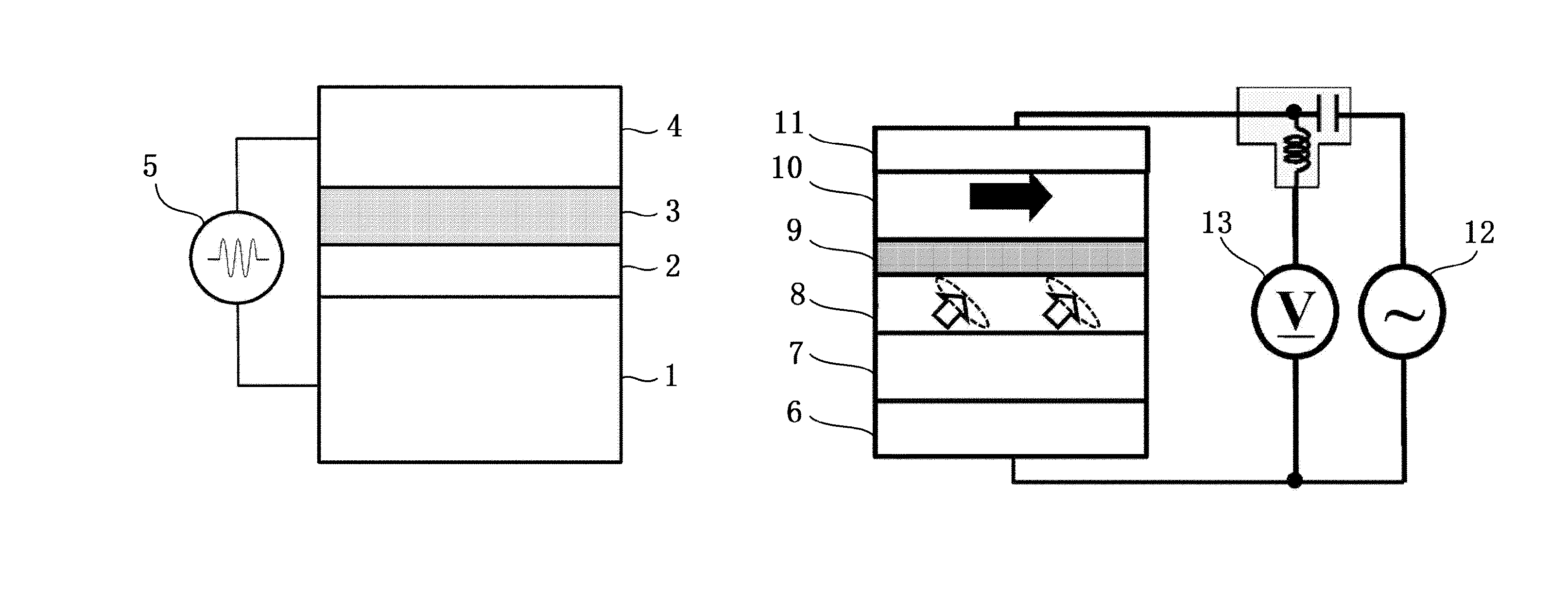
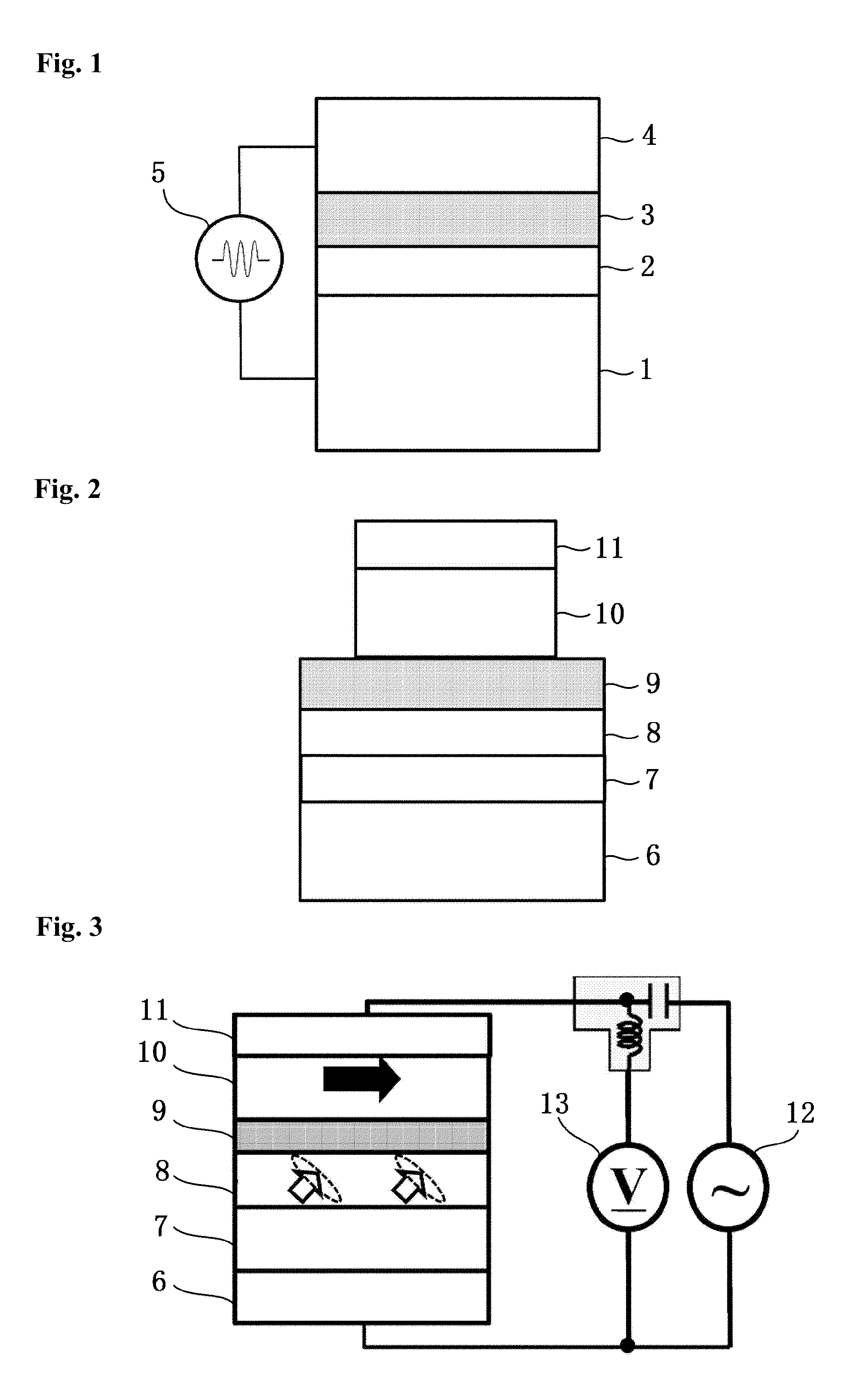
[0113]FIG. 2 is a schematic diagram of a structure of a tunnel junction element in Embodiment 1 used in an experiment. A buffer layer 6, an Au layer 7 (50 nm) as the magnetic anisotropy control layer, an ultrathin FeCo layer 8 (0.54 nm) as the ultrathin ferromagnetic layer, an MgO insulation barrier layer 9 (1.9 nm), an upper Fe layer 10 (10 nm), and a cap layer 11 also serving as the electrode layer are stacked in order on an MgO(001) substrate using molecular beam epitaxy. The sides of the cap layer 11 and the upper Fe layer 10 are etched up to the MgO barrier layer 9 for microfabrication, to form a micro tunnel junction element of 1×1 μm2 in cross section.

[0114]The resistance-area (RA) value is approximately 9.2 kΩμm2, which is designed so that the influence (current magnetic field or spin angular momentum transfer effect) of the current on resonance excitation is sufficiently negligible.

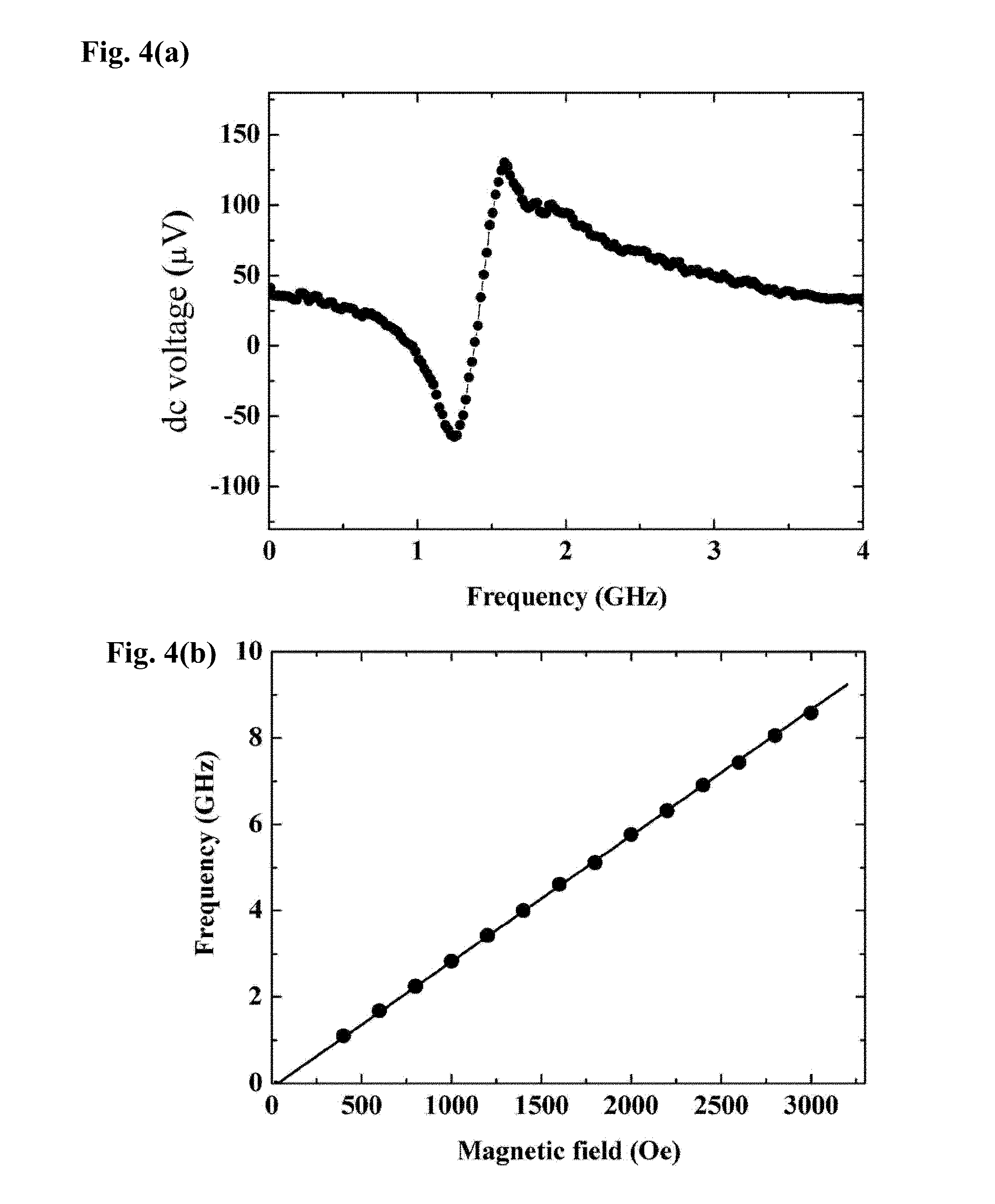
[0115]As shown in FIG. 3, homodyne detection is employed to detect ferromagnetic resonance ex...

embodiment 2

[0136]FIG. 8 is a diagram showing a basic structure for implementing an electric field-driven type ferroelectric resonance excitation method according to Embodiment 2 of the present invention. A bias magnetic layer 14 is provided below the magnetic anisotropy control layer 1, in addition to the basic structure in FIG. 1. By using a leakage magnetic field from the bias magnetic layer 14, a predetermined fixed magnetic field can be applied to the ultrathin ferromagnetic layer 2 without applying the magnetic field from outside.

[0137]This bias magnetic layer 14 does not necessarily need to be adjacent to the magnetic anisotropy control layer 1, and may be provided on the upper side of the element above the insulation barrier layer 3. Specific examples of the material applicable to the bias magnetic layer 14 include: Fe, Co, or Ni; an alloy layer including at least one of these elements; a layer made of a compound, an alloy, or the like including a rare-earth element such as Nd, Sm, or T...

embodiment 3

[0140]FIG. 9 is a diagram showing a basic structure of a spin wave signal generation element using an electric field-driven type ferromagnetic resonance excitation method according to Embodiment 3. The spin wave signal generation element includes the upper electrode layer 4 only in one part, and performs the above-mentioned ferromagnetic resonance excitation by the electric field between the upper electrode layer 4 and the magnetic anisotropy control layer 1. As a result, ferromagnetic resonance is excited only in the area of the ultrathin ferromagnetic layer 2 directly below the upper electrode layer 4. This ferromagnetic resonance excitation propagates in the ultrathin ferromagnetic layer 2 as a spin wave, via exchange interaction, dipolar interaction, or the combination thereof. That is, the ultrathin ferromagnetic layer 2 continuous with the ferromagnetic resonance excitation part serves as a spin wave transmission path. Structures of various magnetic function elements described...


PUM

PropertyMeasurementUnit
tunnel current densityaaaaaaaaaa
current densityaaaaaaaaaa
electric field strengthaaaaaaaaaa

Abstract

To realize an electric field-driven type ferromagnetic resonance excitation method of low power consumption using an electric field as drive power, and provide a spin wave signal generation element and a spin current signal generation element using the method, a logic element using the elements, and a magnetic function element such as a high-frequency detection element and a magnetic recording device using the method. A magnetic field having a specific magnetic field application angle and magnetic field strength is applied to a laminate structure in which an ultrathin ferromagnetic layer sufficiently thin so that an electric field shield effect by conduction electrons does not occur and a magnetic anisotropy control layer are directly stacked on each other and an insulation barrier layer and an electrode layer are arranged in order on an ultrathin ferromagnetic layer side. An electric field having a high-frequency component of a magnetic resonance frequency is then applied between the magnetic anisotropy control layer and the electrode layer, thereby efficiently exciting ferromagnetic resonance in the ultrathin ferromagnetic layer.

Description

RELATED CASE INFORMATION[0001]This application is a 371 U.S. National Stage of International Application No. PCT / JP2012 / 065539, filed on Jun. 18, 2012, which is incorporated by reference herein in its entirety.TECHNICAL FIELD[0002]The present invention is based on a proposition of an electric field-driven type ferromagnetic resonance excitation method, and relates to a spin wave signal generation element for generating a spin wave signal and a spin current signal generation element for generating a spin current signal using the ferromagnetic resonance excitation method, and further to a magnetic function element and the like such as a function element, a logic element, a high-frequency detection element, and a magnetic recording device employing the above-mentioned method and elements.BACKGROUND ART[0003]A technology that forms the basis of current electronic information processing devices is the CMOS (Complementary Metal Oxide Semiconductor) technology, and continuous manufacturing...

Claims


Application Information

Patent Timeline
Patent Type & Authority Patents(United States)
IPC IPC(8): G11B5/147H01L29/66G11C11/16H01L43/08B82Y40/00H01F41/30H03B15/00H01F10/32
CPCG11C11/1675B82Y40/00G11B5/147H01F10/329H01F41/303H01L29/66984H01L43/08H03B15/006H01F10/3254H01F10/3286G11C11/2275H10N50/10
Inventor NOZAKI, TAKAYUKISUZUKI, YOSHISHIGE
Owner NAT INST OF ADVANCED IND SCI & TECH
Why Eureka
Try Eureka