Electric field ferromagnetic resonance excitation method and magnetic function element employing same
- Summary
- Abstract
- Description
- Claims
- Application Information
AI Technical Summary
Benefits of technology
Problems solved by technology
Method used
Image
Examples
embodiment 1
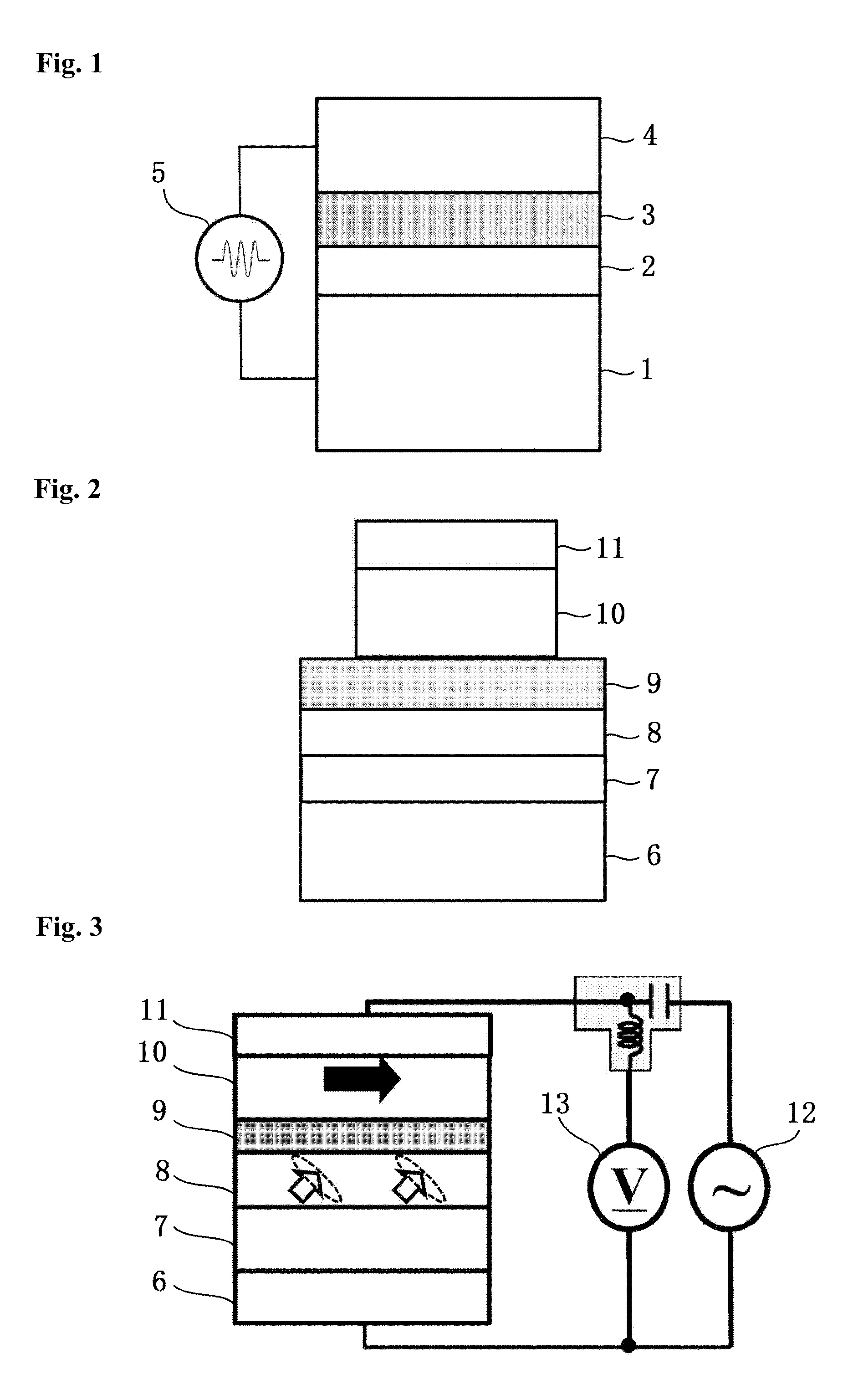
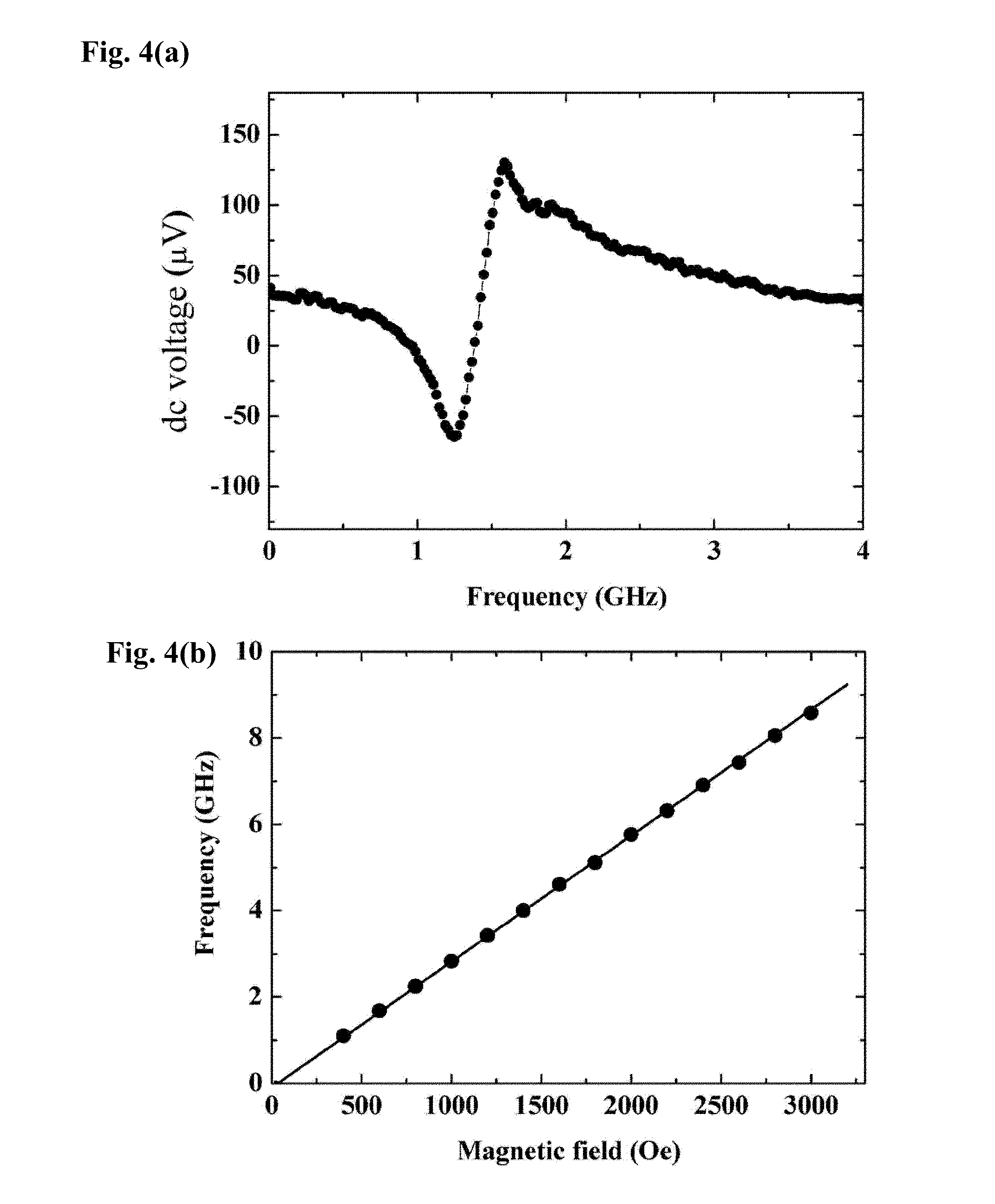
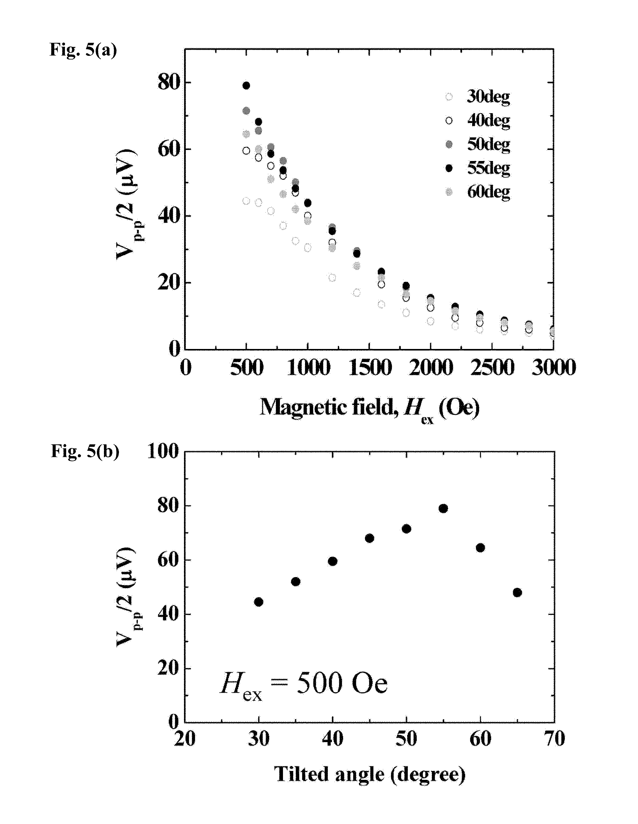
[0112]FIG. 2 is a schematic diagram of a structure of a tunnel junction element in Embodiment 1 used in an experiment. A buffer layer 6, an Au layer 7 (50 nm) as the magnetic anisotropy control layer, an ultrathin FeCo layer 8 (0.54 nm) as the ultrathin ferromagnetic layer, an MgO insulation barrier layer 9 (1.9 nm), an upper Fe layer 10 (10 nm), and a cap layer 11 also serving as the electrode layer are stacked in order on an MgO(001) substrate using molecular beam epitaxy. The sides of the cap layer 11 and the upper Fe layer 10 are etched up to the MgO barrier layer 9 for microfabrication, to form a micro tunnel junction element of 1×1 μm2 in cross section.
[0113]The resistance-area (RA) value is approximately 9.2 kΩμm2, which is designed so that the influence (current magnetic field or spin angular momentum transfer effect) of the current on resonance excitation is sufficiently negligible.
[0114]As shown in FIG. 3, homodyne detection is employed to detect ferromagnetic resonance ex...
embodiment 2
[0135]FIG. 8 is a diagram showing a basic structure for implementing an electric field-driven type ferroelectric resonance excitation method according to Embodiment 2 of the present invention. A bias magnetic layer 14 is provided below the magnetic anisotropy control layer 1, in addition to the basic structure in FIG. 1. By using a leakage magnetic field from the bias magnetic layer 14, a predetermined fixed magnetic field can be applied to the ultrathin ferromagnetic layer 2 without applying the magnetic field from outside.
[0136]This bias magnetic layer 14 does not necessarily need to be adjacent to the magnetic anisotropy control layer 1, and may be provided on the upper side of the element above the insulation barrier layer 3. Specific examples of the material applicable to the bias magnetic layer 14 include: Fe, Co, or Ni; an alloy layer including at least one of these elements; a layer made of a compound, an alloy, or the like including a rare-earth element such as Nd, Sm, or T...
embodiment 3
[0139]FIG. 9 is a diagram showing a basic structure of a spin wave signal generation element using an electric field-driven type ferromagnetic resonance excitation method according to Embodiment 3. The spin wave signal generation element includes the upper electrode layer 4 only in one part, and performs the above-mentioned ferromagnetic resonance excitation by the electric field between the upper electrode layer 4 and the magnetic anisotropy control layer 1. As a result, ferromagnetic resonance is excited only in the area of the ultrathin ferromagnetic layer 2 directly below the upper electrode layer 4. This ferromagnetic resonance excitation propagates in the ultrathin ferromagnetic layer 2 as a spin wave, via exchange interaction, dipolar interaction, or the combination thereof. That is, the ultrathin ferromagnetic layer 2 continuous with the ferromagnetic resonance excitation part serves as a spin wave transmission path. Structures of various magnetic function elements described...
PUM
 Abstract
Description
Claims
Application Information
 - R&D
- Intellectual Property
- Life Sciences
- Materials
- Tech Scout
- Unparalleled Data Quality
- Higher Quality Content
- 60% Fewer Hallucinations
Browse by: Latest US Patents, China's latest patents, Technical Efficacy Thesaurus, Application Domain, Technology Topic, Popular Technical Reports.
© 2025 PatSnap. All rights reserved.Legal|Privacy policy|Modern Slavery Act Transparency Statement|Sitemap|About US| Contact US: help@patsnap.com


