Method and arrangement for building metallic objects by solid freeform fabrication

a technology of freeform fabrication and solid structure, applied in the direction of chemical vapor deposition coating, process and machine control, program control, etc., can solve the problem of limiting the application of ti to the effect of reducing the sensitivity of the ti layer, affecting the accuracy of the welding technique, and affecting the ti layer

Active Publication Date: 2016-11-01
NORSK TITANIUM
View PDF39 Cites 26 Cited by
  • Summary
  • Abstract
  • Description
  • Claims
  • Application Information

AI Technical Summary

Benefits of technology

[0036]The term “plasma transferred arc torch” or “PTA-torch” as used interchangeably herein means any device able to heat and excite a stream of inert gas to plasma by an electric arc discharge and then transfer the flow of plasma gas including the electric arc out through an orifice (nozzle) to form a constricted plume which extends out of the orifice and transfers the intense heat of the arc to a target region. The electrode and target region is electrically connected to a direct current power source such that the electrode of the PTA-torch becomes the cathode and the target region becomes the anode. This will ensure that the plasma plume including electric arc is delivering a highly concentrated heat flow to a small surface area of the target region with excellent control of the areal extension and magnitude of the heat flux being supplied from the PTA-torch. A plasma transferred arc has the advantage of providing stable and consistent arcs with little wandering and good tolerance for length deviations between the cathode and anode. Thus, the PTA-torch is suitable both for forming a molten pool in the base material and to heat and melt the metallic wire feed. The PTA-torch may advantageously have an electrode made of tungsten and a nozzle made of copper. However, the invention is not tied to any specific choice or type of PTA-torch. Any known or conceivable device able to function as PTA-torch may be applied.
[0037]The use of a separately controlled first PTA-torch to preheat the base material and form the molten pool and a separately second PTA-torch to melt the feed wire of metallic material provides the advantage that it becomes possible to increase the heat supply to the feed of the metallic wire independently of the heat supply to the substrate such that it becomes possible to increase the heat flux into the feed material with no risk of creating a “spray arc” which generates spatter. Thus, it is possible to increase the deposition rate of the molten metallic feed material without simultaneously over-heating the substrate and without risk of spatter or form an excessive molten pool and thus, loose control of the consolidation of the deposited material. This feature is obtained by connecting a direct current power source such that the electrode of the first PTA-torch becomes the negative polarity and the base material becomes the positive polarity to define an electric circuit where electric charge is transferred by an arc discharge between the electrode of the first PTA-torch and the base material, and by connecting the electrode of the second PTA-torch to the negative pole of a direct current power source and the feed wire of metallic material to the positive pole to form an electric circuit where electric charge is transferred by an arc discharge between the electrode of the second PTA-torch and the feed wire of metallic material.
[0040]The feed rate (the wire speed) and positioning of the feed wire of metallic material may advantageously be controlled and regulated in accordance with the effect of the power supply to the second PTA-torch in order to ensure that the wire is being continuously heated and melted when reaching the intended position above the molten pool in the base material. This may be obtained by using a conventional gas metal arc welding torch (GMAW-torch, also denoted MIG-torch) as wire feeder without forming an arc in the MIG-torch. This embodiment of the wire feeder has the advantage of being able to electrically connect the wire to the DC power supply of the second PTA-torch and also to position the wire very accurately. The feed wire of metallic material may have any practically implementable dimension, such as i.e. 1.0 mm, 1.6 mm, 2.4 mm, etc.

Problems solved by technology

The accuracy of the welding technique is usually too coarse to allow directly forming the object with acceptable dimensions.
The electron beam technology has a disadvantage of being dependent upon a high vacuum of 10−1 Pa or less in the deposition chamber.
Gas metal arc techniques have several disadvantages that severely limit their application to depositing Ti.
These drawbacks include instabilities in metal transfer, excessive spatter, and poor control of the deposited layer shape, and high heat input that causes distortion of thin sections during deposition.
Also, an increase in productivity is not possible because of wandering of the cathode spot that occurs during deposition.

Method used


Image

  • Method and arrangement for building metallic objects by solid freeform fabrication
  • Method and arrangement for building metallic objects by solid freeform fabrication
  • Method and arrangement for building metallic objects by solid freeform fabrication

Examples


first example embodiment

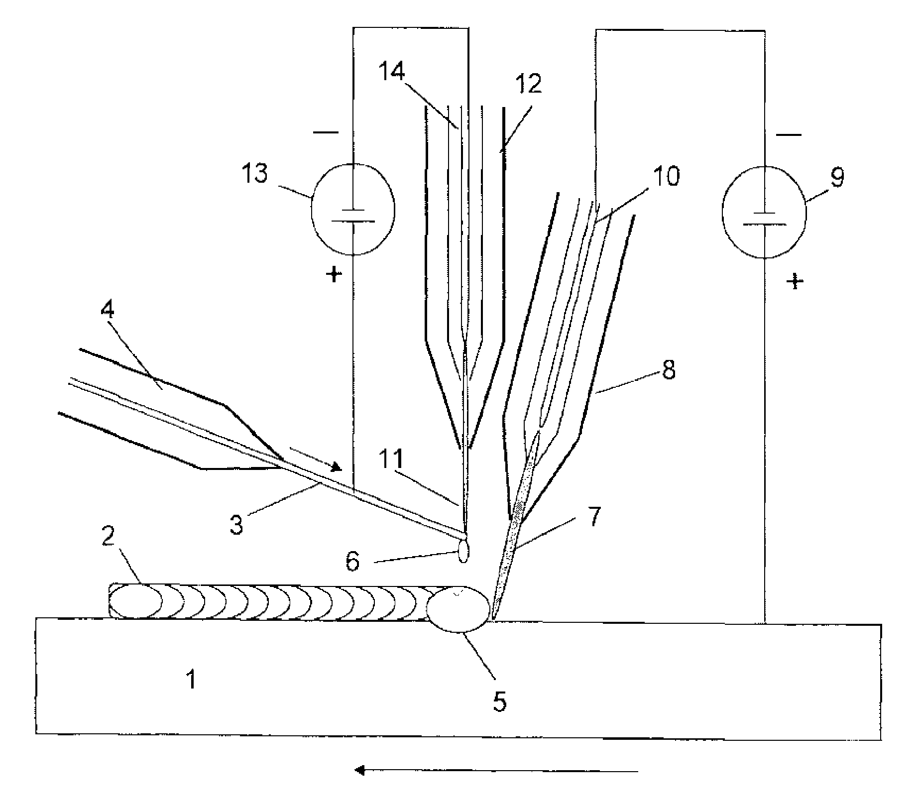
[0049]The first example embodiment of the arrangement according to second aspect of the invention is shown schematically in FIG. 3. The figure shows a holding substrate 1 made of a Ti-6Al-4V alloy shaped as a rectangular cuboid, onto which a three-dimensional object made of the same Ti-6Al-4V alloy is to be formed by solid freeform fabrication. The figure displays the initial part of the deposition process where the first welding stripe 2 of Ti-6Al-4V alloy is being deposited.

[0050]A wire 3 made of the Ti-6Al-4V alloy is continuously being supplied by a wire feeder 4 which positions the wire 3 such that its distal end is located above the molten pool 5 at the deposition area on the holding substrate 1. The wire 3 is given a velocity indicated by the upper arrow on the Figure which corresponds to the heating and melting rate of the distal end such that droplets 6 of molten wire are continuously being supplied to the molten pool 5.

[0051]A first plasma transferred arc 7 is formed by a ...

second example embodiment

[0053]The second example embodiment of the invention is the first example embodiment given above including additional means for forming thermal pulses in the molten pool 5.

[0054]The means for forming thermal pulses is a DC power source 15 which is electrically connected to the second PTA-torch 12 such that the electrode 14 becomes the cathode and the holding substrate 1 becomes the anode. In addition, there are means 16 for pulsing the power delivered by DC power source 15 such that the arc 11 will in addition to heat and melt the wire 3, enter into the molten pool 5 with the same frequency as the pulsed power supply and thus deliver a pulsating heat flux to the molten pool. The means 16 may is regulated by the control system and provides a pulsing arc discharge into the molten pool with a frequency of 1 kHz.


PUM

PropertyMeasurementUnit
frequencyaaaaaaaaaa
diameteraaaaaaaaaa
diameteraaaaaaaaaa

Abstract

A method and arrangement for manufacturing objects by solid freeform fabrication, especially titanium and titanium alloy objects, wherein the deposition rate is increased by supplying the metallic feed material in the form of a wire and employing two gas transferred arcs, one plasma transferred arc for heating the deposition area on the base material and one plasma transferred arc for heating and melting the feed wire.

Description

[0001]This invention relates to a method and arrangement for manufacturing objects by solid freeform fabrication, especially titanium and titanium alloy objects.BACKGROUND[0002]Structured metal parts made of titanium or titanium alloys are conventionally made by casting, forging or machining from a billet. These techniques have a disadvantage of high material use of the expensive titanium metal and large lead times in the fabrication.[0003]Fully dense physical objects may be made by a manufacturing technology known as rapid prototyping, rapid manufacturing, layered manufacturing or additive fabrication. This technique employs computer aided design software (CAD) to first construct a virtual model of the object which is to be made, and then transform the virtual model into thin parallel slices or layers, usually horizontally oriented. The physical object may then be made by laying down successive layers of raw material in the form of liquid paste, powder or sheet material resembling ...

Claims


Application Information

Patent Timeline
Patent Type & Authority Patents(United States)
IPC IPC(8): C23C16/513C23C16/52B23K10/02B22F3/10B23K10/00B23K9/04B33Y50/00B33Y30/00B33Y10/00B22F3/105
CPCB33Y50/00C23C16/513C23C16/52B22F3/105B22F3/1055B23K9/042B23K10/027B33Y10/00B33Y30/00Y02P10/295B23K2103/14C22C14/00Y02P10/25B22F2998/10B22F2999/00B23K10/006B23K15/0026B23K15/0033B23K15/0086B23K15/10B23K26/0608B23K26/342B23K26/348B23K26/60B23K26/702B29C64/153B33Y50/02G05B19/4099G05B2219/35134G05B2219/45135B22F12/33B22F10/362B22F10/32B22F12/13B22F12/47B22F12/48B22F10/25B22F10/22B22F12/17B22F12/43B22F10/80Y02P90/02B33Y40/10B33Y40/00B22F3/115B22F12/70B22F2201/20B22F12/41B22F2202/06B22F2202/13B23K9/1675B23K9/04B23K10/02B23K26/34B23K9/133B23K28/02B23K9/044B23K9/08B23K9/09B23K9/1006B23K9/125B23K9/167B23K9/173B23K9/23
Inventor STEMPFER, FERDINAND
Owner NORSK TITANIUM
Why Eureka
Try Eureka