
Plastic substrate, method for producing the same and touch screen panel containing the same

a technology of touch screen panel and substrate, which is applied in the direction of conductive layers on insulating supports, synthetic resin layered products, metallic pattern materials, etc., can solve the problems of low response speed, one point and is in danger of being damaged, and difficulty in mounting, so as to simplify the structure of the touch screen panel, the effect of low surface resistance and high hardness characteristics

Active Publication Date: 2017-07-11
KOLON IND INC
View PDF13 Cites 17 Cited by
  • Summary
  • Abstract
  • Description
  • Claims
  • Application Information

AI Technical Summary

Benefits of technology

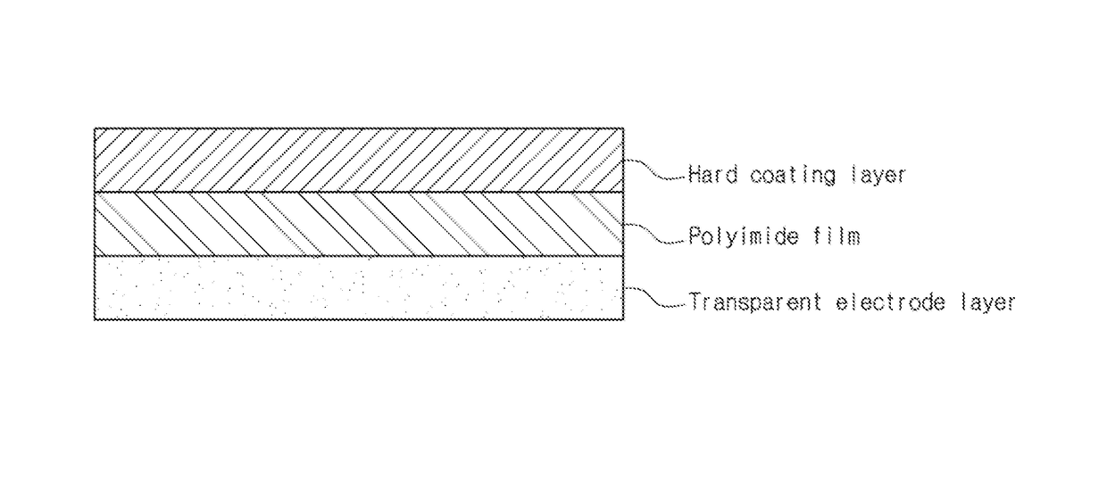
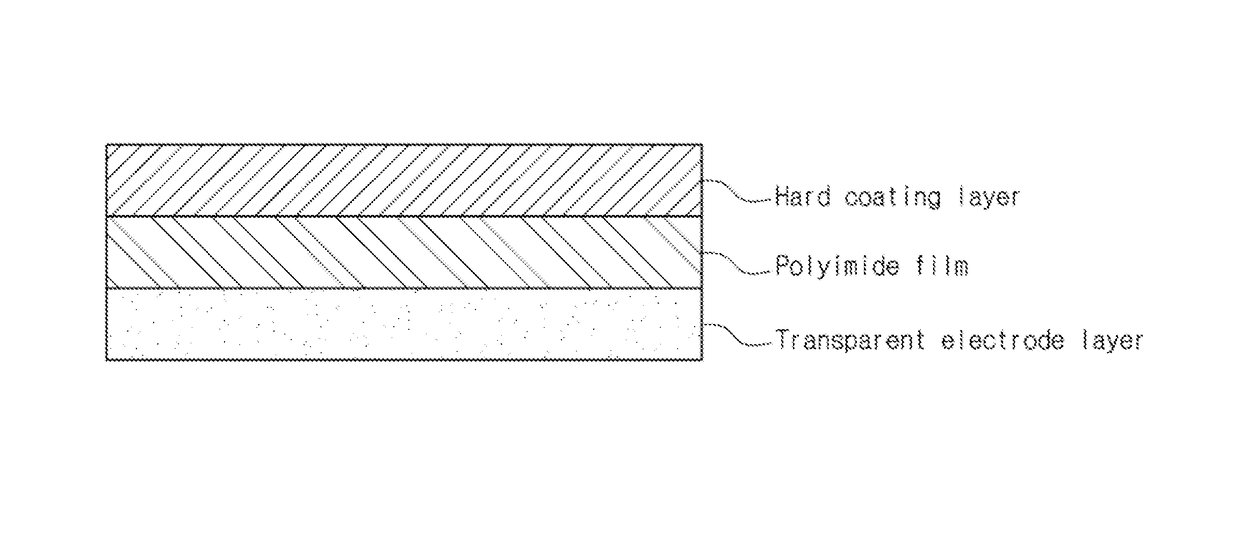
The present invention relates to a plastic substrate that can be used in touch screen panels and other optical applications. The plastic substrate has high hardness, low surface resistance, and does not yellow during the process of being coated with ITO (which is commonly used in touch screen panels). The substrate includes a polyimide film with a low yellowness (measured by a UV spectrometer) and a hard coating layer that improves its chemical resistance. The substrate also has a transparent electrode layer, such as ITO or IZO, for use in touch screen panels. This invention provides a more robust and transparent plastic substrate for use in various optical applications.

Problems solved by technology

However, the glass substrate is problematic in that it is not suitable as a substrate for flexible displays because it is excessively rigid, that is to say, its flexibility is poor.
However, such a substrate for flexible displays, made of a plastic material, has not been developed yet to such a degree that it is commercially available.
This resistive type touch screen panel is advantageous in that it has high resolution and rapid response speed because it is operated by surface pressure, but is disadvantageous in that it can activate only one point and is in danger of being damaged.
This capacitive type touch screen panel is advantageous in that it can be activated by simultaneously pushing several points and has high resolution and excellent durability, but is disadvantageous in that it has a low response speed and is difficult to mount.
In this case, this resistive type touch screen panel is problematic in that its light transmittance is deteriorated due to a lamination process of attaching the first ITO film to the window film (or overlay film) using an optical clear adhesive (OCA), and in that processing treatment becomes complicated and processing cost increases because a process of disposing the window film (or overlay film) and a process of attaching the first ITO film to the window film (or overlay film) using the optical clear adhesive (OCA) must be separately carried out.
Further, this resistive type touch screen panel is problematic in that ITO cannot be selectively applied onto the desired region of the window film (or PET film) because the ITO film is patterned by wet etching using laser.
However, the PET film is advantageous in terms of a cost, but is disadvantageous in that it has low heat resistance to such a degree that it is deformed at 130° C. or higher.
Therefore, when a subsequent heat treatment process is carried out with a PET film deposited with an indium tin oxide (ITO) film, the PET film is expanded or contracted, thus causing the ITO film to become loose or to be cracked.
However, this method is also problematic in that such a pretreatment process serves to increase the time taken to manufacture a touch screen, thus decreasing the production rate thereof.

Method used


Image

  • Plastic substrate, method for producing the same and touch screen panel containing the same
  • Plastic substrate, method for producing the same and touch screen panel containing the same

Examples


examples 1 to 3

[0060]As a reactor, a 100 mL 3-neck round-bottom flask provided with a stirrer, a nitrogen injector, a dropping funnel, a temperature controller and a cooler was filled with 28.78 g of N,N-dimethylacetamide (DMAc) while supplying nitrogen, and then cooled to 0° C., and then 3.2023 g (0.01 mol) of 2,2-TFDB was dissolved in DMAc to prepare a solution, and then this solution was maintained at 0° C. Then, 0.88266 g (0.003 mol) of BPDA was added to the solution and stirred for 1 hour to completely dissolve BPDA, and then 3.10975 g (0.007 mol) of 6FDA was added and completely dissolved. In this case, the concentration of solid matter in the resultant solution was 20 wt %. Thereafter, this solution was stirred at room temperature for 8 hours to obtain a polyamic acid solution having a solution viscosity of 2100 poise at 23° C.

[0061]Subsequently, 2˜4 equivalents of acetic anhydride (acetic oxide, manufactured by Samjeon Co., Ltd.), as a curing agent, and 2˜4 equivalents of pyridine (manufac...

example 4

[0065]As a reactor, a 100 mL 3-neck round-bottom flask provided with a stirrer, a nitrogen injector, a dropping funnel, a temperature controller and a cooler was filled with 28.78 g of N,N-dimethylacetamide (DMAc) while supplying nitrogen, and then cooled to 0° C., and then 3.2023 g (0.01 mol) of 2,2-TFDB was dissolved in DMAc to prepare a solution, and then this solution was maintained at 0° C. Then, 0.88266 g (0.003 mol) of BPDA was added to the solution and stirred for 1 hour to completely dissolve BPDA, and then 1.33275 g (0.003 mol) of 6FDA was added and completely dissolved. Then, 0.8121 g (0.004 mol) of TPC was added to the resultant solution to obtain a polyamic acid solution having a solid content of 15 wt %.

[0066]A plastic substrate film was formed in the same manner as in Example 1 using the obtained polyamic acid solution.

[0067]The thicknesses of the polyimide film, hard coating layer and ITO electrode layer obtained in Example 4 are summarized in Table 1 below.

example 5

[0068]A polyamic acid solution was prepared in the same manner as in Example 1, except that 6FCDA (9,9-bis(trifluoromethyl)-2,3,6,7-xanthene tetracarboxyl dianhydride) was used as a composition for preparing the same instead of 6FDA. Then, a plastic substrate film was formed using the prepared polyamic acid solution in the same manner as in Example 1.

[0069]The thicknesses of the polyimide film, hard coating layer and ITO electrode layer obtained in Example 5 are summarized in Table 1 below.


PUM

PropertyMeasurementUnit
light transmittanceaaaaaaaaaa
yellownessaaaaaaaaaa
thicknessaaaaaaaaaa

Abstract

The present invention provides a plastic substrate, including: a polyimide film; a hard coating layer formed on one side of the polyimide film; and a transparent electrode layer formed on the other side of the polyimide film. The plastic substrate has excellent light transmittance high hardness characteristics, superior ITO processability and flexibility. Further, the plastic substrate can function as both a window film and an electrode film when it is applied to a touch screen panel. Thus, the present invention provides a touch screen panel which can be slimmed by reducing the number of laminated films including the plastic substrate.

Description

CROSS REFERENCE TO RELATED APPLICATIONS[0001]This is a National Stage of International Application No. PCT / KR2012 / 011459 filed Dec. 26, 2012, claiming priority based on Korean Patent Application No. 10-2011-0142075 filed Dec. 26, 2011, the contents of all of which are incorporated herein by reference in their entirety.TECHNICAL FIELD[0002]The present invention relates to a plastic substrate and a touch screen panel including the same.BACKGROUND ART[0003]Recently, in displays, conventional cathode ray tubes (CRTS) have been converted into flat panel displays, such a plasma display panel (PDP), a liquid crystal display (LCD), an organic light emitting diode (OLED) and the like. Particularly, in order to realize such flat panel displays into flexible displays in the future, research thereinto is going on all over the world.[0004]In such a flat panel display, basically, a substrate is made of a glass material. Meanwhile, in a general flat panel display, high-temperature heat treatment i...

Claims


Application Information

Patent Timeline
Patent Type & Authority Patents(United States)
IPC IPC(8): H05K1/00H05K1/02H05K1/09C08J5/18H01B3/30C08J7/04H05K1/03G06F3/041C08J7/043C08J7/046
CPCH05K1/0353C08J5/18C08J7/045G06F3/041H01B3/30H01B3/306H05K1/0274H05K1/092C08J2379/08C08J2433/06C08J2475/04C08J2483/16G06F2203/04103C08J7/0423C08J7/043C08J7/046B32B27/00H01B5/14
Inventor JUNG, HAK GEEPARK, HYO JUNJU, CHUL HA
Owner KOLON IND INC
Learn More